In the latest article we’ve discussed the implementation of inter-VRF leaking using two regular EPGs. Naturally, it’s possible to use an L3Out in shared service design – for instance, to provide common Internet access. However, the ACI Contract whitepaper has a section that highlights a rather peculiar limitation with an L3Out:
“Due to CSCvm63145, an EPG in a preferred group can consume an inter-VRF contract, but cannot be a provider for an inter-VRF contract with an L3Out EPG as the consumer.”
There is no further explanation of such a state of affairs. If you check out the detect itself, it sheds a bit more light on what goes wrong: if an EPG is a provider for inter-VRF contract, then it cannot communicate within Preferred Group because of some restrictive zoning filter. However, shouldn’t the interaction between EPGs be governed by an explicit contract in the first place? Let’s test such a setup and see ourselves:

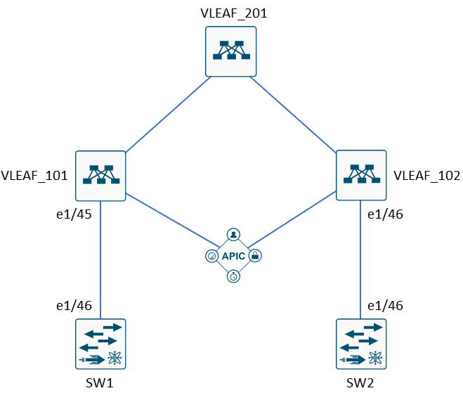
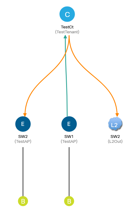
Host emulates 3 entities: provider of a service (Provider), consumer of that service (L3Out) and some other endpoint (TestEPG) that is part of the Preferred Group in TestVrf1. L3Out uses OSPF to exchange prefixes. 2.2.2.2/32 is expected to use the service located at 192.168.1.1. Meanwhile, both Provider and TestEPG are in the same subnet, thus same BD.
Here is the configuration of Access Policy section to allow physical connectivity:
resource "aci_vlan_pool" "TestPool" {
  name  = "TestPool"
  alloc_mode  = "static"
}
resource "aci_ranges" "TestRange" {
  vlan_pool_dn  = aci_vlan_pool.TestPool.id
  from = "vlan-1"
  to = "vlan-1000"
  alloc_mode = "static"
}
resource "aci_physical_domain" "PhysicalDomain" {
  name = "PhysicalDomain"
  relation_infra_rs_vlan_ns = aci_vlan_pool.TestPool.id
}
resource "aci_l3_domain_profile" "L3Domain" {
  name = "L3Domain"
  relation_infra_rs_vlan_ns = aci_vlan_pool.TestPool.id
}
resource "aci_attachable_access_entity_profile" "TestAAEP" {
    name = "TestAAEP"
}
resource "aci_aaep_to_domain" "PhysicalDomain-to-TestAAEP" {
  attachable_access_entity_profile_dn = aci_attachable_access_entity_profile.TestAAEP.id
  domain_dn = aci_physical_domain.PhysicalDomain.id
}
resource "aci_aaep_to_domain" "L3Domain-to-TestAAEP" {
  attachable_access_entity_profile_dn = aci_attachable_access_entity_profile.TestAAEP.id
  domain_dn = aci_l3_domain_profile.L3Domain.id
}
resource "aci_leaf_interface_profile" "TestInterfaceProfile" {
    name = "TestInterfaceProfile"
}
resource "aci_access_port_block" "TestAccessBlockSelector" {
  access_port_selector_dn = aci_access_port_selector.TestAccessPortSelector.id
  name = "TestAccessBlockSelector"
  from_card = "1"
  from_port = "2"
  to_card = "1"
  to_port = "4"
}
resource "aci_access_port_selector" "TestAccessPortSelector" {
    leaf_interface_profile_dn = aci_leaf_interface_profile.TestInterfaceProfile.id
    name = "TestAccessPortSelector"
    access_port_selector_type = "range"
    relation_infra_rs_acc_base_grp = aci_leaf_access_port_policy_group.TestAccessInterfacePolicy.id
}
resource "aci_leaf_access_port_policy_group" "TestAccessInterfacePolicy" {
    name = "TestAccessInterfaceProfile"
    relation_infra_rs_att_ent_p = aci_attachable_access_entity_profile.TestAAEP.id
}
resource "aci_leaf_profile" "TestSwitchProfile" {
  name = "TestSwitchProfile"
  leaf_selector {
    name = "LeafSelector"
    switch_association_type = "range"
    node_block {
      name  = "Block1"
      from_ = "101"
      to_   = "104"
    }
  }
  relation_infra_rs_acc_port_p = [aci_leaf_interface_profile.TestInterfaceProfile.id]
}
After that we can define a tenant, containing required EPGs and network entities:
resource "aci_tenant" "TestTenant" {
name = "TestTenant"
}
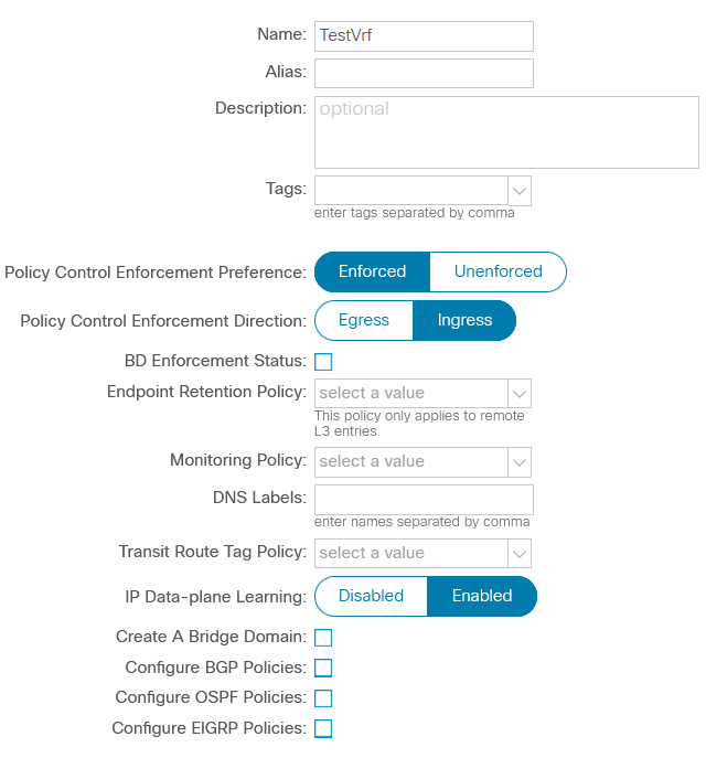
resource "aci_vrf" "TestVrf1" {
tenant_dn = aci_tenant.TestTenant.id
name = "TestVrf1"
}
resource "aci_vrf" "TestVrf2" {
tenant_dn = aci_tenant.TestTenant.id
name = "TestVrf2"
}
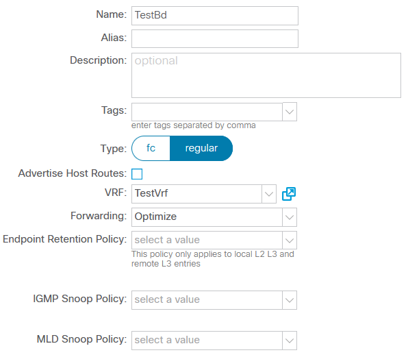
resource "aci_bridge_domain" "TestBD1" {
tenant_dn = aci_tenant.TestTenant.id
name = "TestBD1"
relation_fv_rs_ctx = aci_vrf.TestVrf1.id
}
resource "aci_subnet" "ProviderSubnet" {
parent_dn = aci_application_epg.Provider.id
ip = "192.168.1.1/32"
scope = ["public", "shared"]
ctrl = ["no-default-gateway"]
}
resource "aci_subnet" "TestEPGSubnet" {
parent_dn = aci_bridge_domain.TestBD1.id
ip = "192.168.1.254/24"
scope = ["public", "shared"]
}
resource "aci_application_profile" "TestAP" {
tenant_dn = aci_tenant.TestTenant.id
name = "TestAP"
}
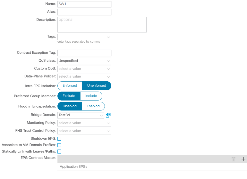
resource "aci_application_epg" "Provider" {
application_profile_dn = aci_application_profile.TestAP.id
name = "Provider"
relation_fv_rs_bd = aci_bridge_domain.TestBD1.id
pref_gr_memb = "include"
}
resource "aci_application_epg" "TestEPG" {
application_profile_dn = aci_application_profile.TestAP.id
name = "TestEPG"
relation_fv_rs_bd = aci_bridge_domain.TestBD1.id
pref_gr_memb = "include"
}
resource "aci_epg_to_domain" "ProviderDomain" {
application_epg_dn = aci_application_epg.Provider.id
tdn = aci_physical_domain.PhysicalDomain.id
}
resource "aci_epg_to_domain" "TestEPGDomain" {
application_epg_dn = aci_application_epg.TestEPG.id
tdn = aci_physical_domain.PhysicalDomain.id
}
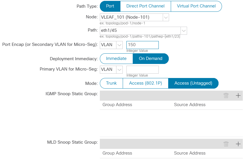
resource "aci_bulk_epg_to_static_path" "ProviderStaticPath" {
application_epg_dn = aci_application_epg.Provider.id
static_path {
interface_dn = "topology/pod-1/paths-101/pathep-[eth1/2]"
encap = "vlan-100"
}
}
resource "aci_bulk_epg_to_static_path" "TestEPGStaticPath" {
application_epg_dn = aci_application_epg.TestEPG.id
static_path {
interface_dn = "topology/pod-1/paths-101/pathep-[eth1/2]"
encap = "vlan-101"
}
}
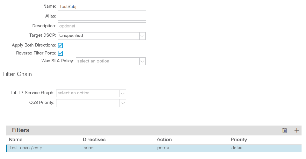
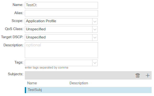
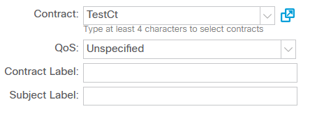
Let’s define a generic contract that permits everything and assign it to Provider:
resource "aci_contract" "TestContract" {
tenant_dn = aci_tenant.TestTenant.id
name = "TestContract"
scope = "tenant"
}
resource "aci_contract_subject" "TestSubject" {
contract_dn = aci_contract.TestContract.id
name = "TestSubject"
}
resource "aci_contract_subject_filter" "PermitIPSubj" {
contract_subject_dn = aci_contract_subject.TestSubject.id
filter_dn = aci_filter.PermitIPFilter.id
}
resource "aci_filter" "PermitIPFilter" {
tenant_dn = aci_tenant.TestTenant.id
name = "PermitIPFilter"
}
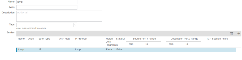
resource "aci_filter_entry" "PermitIPFilterEntry" {
filter_dn = aci_filter.PermitIPFilter.id
name = "demo_entry"
d_to_port = "unspecified"
ether_t = "ip"
}
resource "aci_application_epg" "Provider" {
application_profile_dn = aci_application_profile.TestAP.id
name = "Provider"
relation_fv_rs_bd = aci_bridge_domain.TestBD1.id
relation_fv_rs_prov = [aci_contract.TestContract.id]
pref_gr_memb = "include"
}
Now we can set up the Host and verify if there is connectivity to the fabric. This way we make sure that the previous steps are successful, and nothing has been missed.
Host# show run vrf Provider
interface Ethernet1/1.100
  vrf member Provider
vrf context Provider
  ip route 0.0.0.0/0 192.168.1.254
  address-family ipv4 unicast
Host#
Host# show vrf Provider interface
Interface                 VRF-Name                        VRF-ID  Site-of-Origin
Ethernet1/1.100           Provider                             3  --
Host#
Host# show run interface e1/1.100
interface Ethernet1/1.100
  encapsulation dot1q 100
  mac-address 0000.0000.0001
  vrf member Provider
  ip address 192.168.1.1/24
Host#
Host# show run vrf TestEPG
interface Ethernet1/1.101
  vrf member TestEPG
vrf context TestEPG
  ip route 0.0.0.0/0 192.168.1.254
  address-family ipv4 unicast
Host#
Host# show vrf TestEPG interface
Interface                 VRF-Name                        VRF-ID  Site-of-Origin
Ethernet1/1.101           TestEPG                              5  --
Host#
Host# show run interface e1/1.101
interface Ethernet1/1.101
  encapsulation dot1q 101
  mac-address 0000.0000.0002
  vrf member TestEPG
  ip address 192.168.1.2/24
Since we use the same physical interface to connect to the fabric, subinterfaces would inherit the same MAC address from it. In such a case ACI would incorrectly consider both IPs to be part of the same endpoint and EPG as a result. The fix is simple – use different MAC addresses so we define them manually.
Host# ping 192.168.1.254 vrf Provider
PING 192.168.1.254 (192.168.1.254): 56 data bytes
64 bytes from 192.168.1.254: icmp_seq=0 ttl=63 time=1.145 ms
64 bytes from 192.168.1.254: icmp_seq=1 ttl=63 time=0.898 ms
64 bytes from 192.168.1.254: icmp_seq=2 ttl=63 time=1.008 ms
64 bytes from 192.168.1.254: icmp_seq=3 ttl=63 time=0.97 ms
64 bytes from 192.168.1.254: icmp_seq=4 ttl=63 time=1.023 ms
--- 192.168.1.254 ping statistics ---
5 packets transmitted, 5 packets received, 0.00% packet loss
round-trip min/avg/max = 0.898/1.008/1.145 ms
Host#
Host# ping 192.168.1.254 vrf TestEPG
PING 192.168.1.254 (192.168.1.254): 56 data bytes
64 bytes from 192.168.1.254: icmp_seq=0 ttl=63 time=1.24 ms
64 bytes from 192.168.1.254: icmp_seq=1 ttl=63 time=0.961 ms
64 bytes from 192.168.1.254: icmp_seq=2 ttl=63 time=1.021 ms
64 bytes from 192.168.1.254: icmp_seq=3 ttl=63 time=0.744 ms
64 bytes from 192.168.1.254: icmp_seq=4 ttl=63 time=0.785 ms
--- 192.168.1.254 ping statistics ---
5 packets transmitted, 5 packets received, 0.00% packet loss
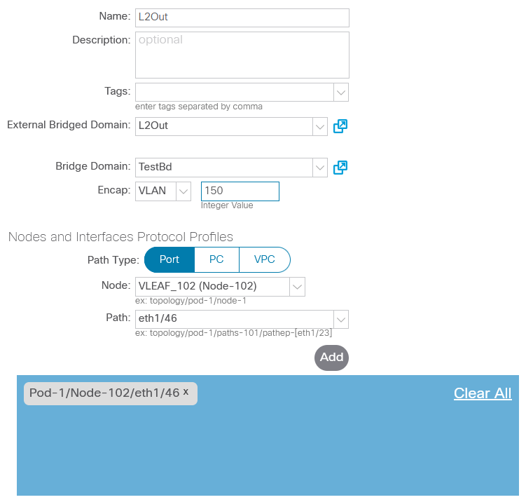
round-trip min/avg/max = 0.744/0.95/1.24 msThe last part of configuration is to create L3Out and assign a contract to it.
resource "aci_l3_outside" "L3Out" {
    tenant_dn = aci_tenant.TestTenant.id
    name = "L3Out"
    enforce_rtctrl = ["export", "import"]
    relation_l3ext_rs_ectx = aci_vrf.TestVrf2.id
    relation_l3ext_rs_l3_dom_att = aci_l3_domain_profile.L3Domain.id
}
resource "aci_logical_node_profile" "L3OutNodeProfile" {
    l3_outside_dn = aci_l3_outside.L3Out.id
    name = "L3OutNodeProfile"
}
resource "aci_logical_interface_profile" "L3OutLogicalInterfaceProfile" {
    logical_node_profile_dn = aci_logical_node_profile.L3OutNodeProfile.id
    name = "L3OutLogicalInterfaceProfile"
}
resource "aci_logical_node_to_fabric_node" "NodetoFabric" {
  logical_node_profile_dn = aci_logical_node_profile.L3OutNodeProfile.id
  tdn = "topology/pod-1/node-103"
  rtr_id = "1.1.1.1"
}
resource "aci_l3out_path_attachment" "InterfaceMapping" {
  logical_interface_profile_dn = aci_logical_interface_profile.L3OutLogicalInterfaceProfile.id
  target_dn = "topology/pod-1/paths-103/pathep-[eth1/3]"
  if_inst_t = "l3-port"
  encap = "unknown"
  addr = "192.168.2.254/24"
}
resource "aci_l3out_ospf_external_policy" "L3OutOSPF" {
  l3_outside_dn = aci_l3_outside.L3Out.id
  area_id = "0.0.0.0"
  area_type = "regular"
}
resource "aci_ospf_interface_policy" "L3OutOSPFPolicy" {
    tenant_dn = aci_tenant.TestTenant.id
    name = "L3OutOSPFPolicy"
    ctrl = ["mtu-ignore"]
    dead_intvl = "40"
    hello_intvl = "10"
}
resource "aci_l3out_ospf_interface_profile" "L3OutOSPFInterface" {
  logical_interface_profile_dn = aci_logical_interface_profile.L3OutLogicalInterfaceProfile.id
  relation_ospf_rs_if_pol = aci_ospf_interface_policy.L3OutOSPFPolicy.id
  auth_key = "key"
}
resource "aci_external_network_instance_profile" "Consumer" {
    l3_outside_dn = aci_l3_outside.L3Out.id
    name = "Consumer"
    relation_fv_rs_cons = [aci_contract.TestContract.id]
}
resource "aci_l3_ext_subnet" "ConsumerSubnet" {
  external_network_instance_profile_dn = aci_external_network_instance_profile.Consumer.id
  ip = "2.2.2.2/32"
  scope = ["import-rtctrl", "import-security", "shared-security", "shared-rtctrl"]
}
Let’s configure OSPF on Host to establish adjacency with ACI:
Host# show run vrf Consumer
interface loopback0
vrf member Consumer
interface Ethernet1/2
vrf member Consumer
vrf context Consumer
address-family ipv4 unicast
router ospf 1
vrf Consumer
Host#
Host# show vrf B interface
Interface VRF-Name VRF-ID Site-of-Origin
loopback0 Consumer 4 --
Ethernet1/2 Consumer 4 --
Host#
Host# show run interface lo0
interface loopback0
vrf member Consumer
ip address 2.2.2.2/32
ip router ospf 1 area 0.0.0.0
Host#
Host# show run interface e1/2
interface Ethernet1/2
no switchport
vrf member Consumer
ip address 192.168.2.1/24
ip ospf mtu-ignore
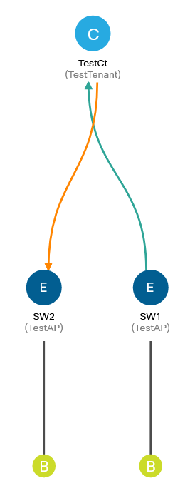
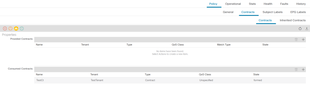
ip router ospf 1 area 0.0.0.0At this point a contract is applied only to Provider and L3Out so there should be connectivity between them. TestEPG, however, should be unreachable by Provider.
Host# ping 192.168.1.2 vrf Provider
PING 192.168.1.2 (192.168.1.2): 56 data bytes
36 bytes from 192.168.1.1: Destination Host Unreachable
Request 0 timed out
Request 1 timed out
Request 2 timed out
Request 3 timed out
Request 4 timed out
--- 192.168.1.2 ping statistics ---
5 packets transmitted, 0 packets received, 100.00% packet loss
Host#
Host# ping 192.168.1.1 vrf Consumer source 2.2.2.2
PING 192.168.1.1 (192.168.1.1) from 2.2.2.2: 56 data bytes
64 bytes from 192.168.1.1: icmp_seq=0 ttl=252 time=1.691 ms
64 bytes from 192.168.1.1: icmp_seq=1 ttl=252 time=1.489 ms
64 bytes from 192.168.1.1: icmp_seq=2 ttl=252 time=1.529 ms
64 bytes from 192.168.1.1: icmp_seq=3 ttl=252 time=1.525 ms
64 bytes from 192.168.1.1: icmp_seq=4 ttl=252 time=1.533 ms
In order to reach Provider from the border leaf, there should be a static route to that EPG that lists the necessary VNID rewrite and ClassID.
Leaf-103# show ip route vrf TestTenant:TestVrf2
<output omitted>
1.1.1.1/32, ubest/mbest: 2/0, attached, direct
    *via 1.1.1.1, Lo6, [0/0], 00:08:30, direct
    *via 1.1.1.1, Lo6, [0/0], 00:08:30, local, local
2.2.2.2/32, ubest/mbest: 1/0
    *via 192.168.2.1, Eth1/3, [110/5], 00:07:41, ospf-default, intra
192.168.1.1/32, ubest/mbest: 1/0, attached, direct, pervasive
    *via 10.0.96.64%overlay-1, [1/0], 00:03:54, static, tag 4294967292
192.168.2.0/24, ubest/mbest: 1/0, attached, direct
    *via 192.168.2.254, Eth1/3, [0/0], 00:08:27, direct
192.168.2.254/32, ubest/mbest: 1/0, attached
    *via 192.168.2.254, Eth1/3, [0/0], 00:08:27, local, local
Leaf-103#
Leaf-103# show ip route vrf TestTenant:TestVrf2 192.168.1.1/32 det
<output omitted>
192.168.1.1/32, ubest/mbest: 1/0, attached, direct, pervasive
    *via 10.0.96.64%overlay-1, [1/0], 00:15:41, static, tag 4294967292
         recursive next hop: 10.0.96.64/32%overlay-1
         vrf crossing information:  VNID:0x288000 ClassId:0x1562 Flush#:0x3
As you would expect, 0x288000 (2654208) is the VNID of TestVrf1:

The ClassID 0x1562 (5474) corresponds to Provider EPG:

External EPG on L3Out also has a global pcTag (5475). Remember that a contract is always enforced on a consumer leaf? Well, ingress enforcement of contract (VRF-level knob) mandates applying contracts on a compute leaf instead of a border leaf. In our case the compute leaf is the provider leaf; in order to enforce the policy on its end, the provider leaf has to know L3Out pcTag, thus L3Out EPG must have a global pcTag.

Feeling confused? Cannot figure out where a policy is applied in the end? Let’s see whether border leaf enforces the policies or not:
Leaf-103# show zoning-rule scope 2818048
+---------+--------+--------+----------+----------------+---------+---------+-------------------------+----------+------------------------+
| Rule ID | SrcEPG | DstEPG | FilterID |      Dir       |  operSt |  Scope  |           Name          |  Action  |        Priority        |
+---------+--------+--------+----------+----------------+---------+---------+-------------------------+----------+------------------------+
|   4102  |   0    |   0    | implarp  |    uni-dir     | enabled | 2818048 |                         |  permit  |   any_any_filter(17)   |
|   4099  |   0    |   0    | implicit |    uni-dir     | enabled | 2818048 |                         | deny,log |    any_any_any(21)     |
|   4098  |   0    |   15   | implicit |    uni-dir     | enabled | 2818048 |                         | deny,log |  any_vrf_any_deny(22)  |
|   4108  |  5474  |   0    | implicit |    uni-dir     | enabled | 2818048 |                         | deny,log | shsrc_any_any_deny(12) |
|   4111  |  5474  |  5475  |    4     | uni-dir-ignore | enabled | 2818048 | TestTenant:TestContract |  permit  |     fully_qual(7)      |
|   4110  |  5475  |  5474  |    4     |     bi-dir     | enabled | 2818048 | TestTenant:TestContract |  permit  |     fully_qual(7)      |
+---------+--------+--------+----------+----------------+---------+---------+-------------------------+----------+------------------------+
The rules in this table are responsible for overall filtering within TestVrf2:
- ID 4102: permits ARP from any to any;
- ID 4099: denies any traffic from any to any;
- ID 4098: denies any traffic from any to 0.0.0.0/0 announced by L3Out (added if there is Preferred Group config);
- ID 4108: denies any traffic from Provider (has global pcTag) to any – always added in consumer VRF to deny traffic that is not covered by a contract (provider VRF just forwards the traffic);
- ID 4110-4111: permits traffic between Provider and L3Out EPG according to filter 4.
It seems we’re done with the border leaf, let’s jump over to the provider leaf.
Leaf-101# show ip route vrf TestTenant:TestVrf1
<output omitted>
2.2.2.2/32, ubest/mbest: 1/0
    *via 10.0.88.68%overlay-1, [200/5], 00:20:18, bgp-65000, internal, tag 65000
192.168.1.0/24, ubest/mbest: 1/0, attached, direct, pervasive, dcs
    *via 10.0.96.64%overlay-1, [1/0], 00:16:31, static
192.168.1.1/32, ubest/mbest: 1/0, attached, direct, pervasive, dcs
    *via 10.0.96.64%overlay-1, [1/0], 00:17:58, static
192.168.1.254/32, ubest/mbest: 1/0, attached, pervasive
    *via 192.168.1.254, Vlan4, [0/0], 00:16:31, local, local

Leaf-101#
Leaf-101# show ip route vrf TestTenant:TestVrf1 2.2.2.2/32 det
<output omitted>
2.2.2.2/32, ubest/mbest: 1/0
    *via 10.0.88.68%overlay-1, [200/5], 00:20:28, bgp-65000, internal, tag 65000
         client-specific data: 1d
         recursive next hop: 10.0.88.68/32%overlay-1
          BGP extended route information: BGP origin AS 65000 BGP peer AS 65000 rw-vnid: 0x2b0000 table-id: 0xe rw-mac: 0
The story is a bit different with compute leaf. External prefixes are exchanged by MP-BGP within the fabric. BGP updates announce the prefixes and corresponding VNIDs so there is no need for static pervasive routes to perform VNID rewrites. ClassID, however, seems to be set statically as there is no relevant information in the BGP output. Besides, pcTag-to-prefix mapping can be obtained by a completely different command:
Leaf-101# show system internal policy-mgr prefix
Requested prefix data

Vrf-Vni VRF-Id Table-Id Table-State  VRF-Name                    Addr                                Class Shared Remote Complete Svc_ena
======= ======  =========== =======  ============================ ================================= ====== ====== ====== ======== ========
2752512 7      0x7           Up     common:default                                       0.0.0.0/0   15      False  False  False    False
2752512 7      0x80000007    Up     common:default                                            ::/0   15      False  False  False    False
2654208 15     0x8000000f    Up     TestTenant:TestVrf1                                       ::/0   15      False  False  False    False
2654208 15     0xf           Up     TestTenant:TestVrf1                                  0.0.0.0/0   15      False  False  False    False
2654208 15     0xf           Up     TestTenant:TestVrf1                                  2.2.2.2/32  5475    True   True   False    False
What about the contracts? Are they applied on provider leaf as well since the global pcTag is allocated for L3Out EPG?
Leaf-101# show zoning-rule scope 2654208
+---------+--------+--------+----------+----------------+---------+---------+-------------------------+-----------------+----------------------+
| Rule ID | SrcEPG | DstEPG | FilterID |      Dir       |  operSt |  Scope  |           Name          |      Action     |       Priority       |
+---------+--------+--------+----------+----------------+---------+---------+-------------------------+-----------------+----------------------+
|   4104  |   0    | 49153  | implicit |    uni-dir     | enabled | 2654208 |                         |      permit     |   any_dest_any(16)   |
|   4101  |   0    |   0    | implarp  |    uni-dir     | enabled | 2654208 |                         |      permit     |  any_any_filter(17)  |
|   4103  |   0    |   0    | implicit |    uni-dir     | enabled | 2654208 |                         |     deny,log    |   any_any_any(21)    |
|   4102  |   0    |   15   | implicit |    uni-dir     | enabled | 2654208 |                         |     deny,log    | any_vrf_any_deny(22) |
|   4113  |  5475  |  5474  |    4     |     bi-dir     | enabled | 2654208 | TestTenant:TestContract |      permit     |    fully_qual(7)     |
|   4115  |  5474  |   14   | implicit |    uni-dir     | enabled | 2654208 |                         | permit_override |    src_dst_any(9)    |
|   4111  |  5474  |  5475  |    4     | uni-dir-ignore | enabled | 2654208 | TestTenant:TestContract |      permit     |    fully_qual(7)     |
+---------+--------+--------+----------+----------------+---------+---------+-------------------------+-----------------+----------------------+
It seems that compute leaf indeed enforces the contact along with border leaf:
- ID 4104: permits any traffic from any to TestBD1 – flooding within BD;
- ID 4101: permits ARP from any to any;
- ID 4103: denies any traffic from any to any;
- ID 4102: denies any traffic from any to 0.0.0.0/0 announced by L3Out (added if there is Preferred Group config);
- ID 4115: permits return traffic from Provider back to consumer VRF;
- ID 4111, 4113: permits traffic between Provider and L3Out EPG according to filter 4.

It doesn’t mean that the policy is enforced twice though. As soon as a policy is applied, SP and DP bits in iVXLAN header are set so there is no double effort. Ambiguity about policy enforcement point – sure, a bit of wasted TCAM – probably, but there should be no double processing involved.
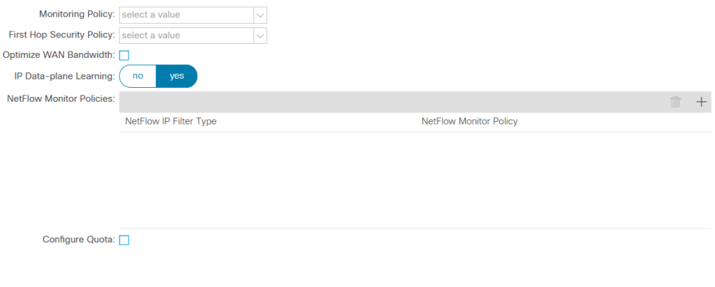
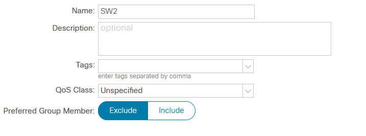
Back to the main topic though. Imagine that TestEPG has to communicate with Provider and there is some kind of restriction that makes contracts not suitable. Preferred Group seems to be the answer since the EPGs do not need a contract to permit traffic between them if they are part of that group. So far we’ve added EPGs to the group but it’s not enabled on VRF level so there is no effect. Let’s enable the feature in GUI as there seems to be no option to do it in Terraform (provider version 2.5.2).

Did it break the connectivity as predicted by white paper?
Host# ping 192.168.1.1 vrf Provider source 2.2.2.2
PING 192.168.1.1 (192.168.1.1) from 2.2.2.2: 56 data bytes
64 bytes from 192.168.1.1: icmp_seq=0 ttl=252 time=1.832 ms
64 bytes from 192.168.1.1: icmp_seq=1 ttl=252 time=1.254 ms
64 bytes from 192.168.1.1: icmp_seq=2 ttl=252 time=1.285 ms
64 bytes from 192.168.1.1: icmp_seq=3 ttl=252 time=1.529 ms
64 bytes from 192.168.1.1: icmp_seq=4 ttl=252 time=1.579 ms

--- 192.168.1.1 ping statistics ---
5 packets transmitted, 5 packets received, 0.00% packet loss
round-trip min/avg/max = 1.254/1.495/1.832 ms
Host#
Host# ping 192.168.1.254 vrf TestEPG
PING 192.168.1.254 (192.168.1.254): 56 data bytes
64 bytes from 192.168.1.254: icmp_seq=0 ttl=63 time=1.256 ms
64 bytes from 192.168.1.254: icmp_seq=1 ttl=63 time=0.943 ms
64 bytes from 192.168.1.254: icmp_seq=2 ttl=63 time=1.002 ms
64 bytes from 192.168.1.254: icmp_seq=3 ttl=63 time=1.02 ms
64 bytes from 192.168.1.254: icmp_seq=4 ttl=63 time=0.993 ms

--- 192.168.1.254 ping statistics ---
5 packets transmitted, 5 packets received, 0.00% packet loss
round-trip min/avg/max = 0.943/1.042/1.256 ms
Host#
Host# ping 192.168.1.2 vrf Provider
PING 192.168.1.2 (192.168.1.2): 56 data bytes
Request 0 timed out
Request 1 timed out
Request 2 timed out
Request 3 timed out
Request 4 timed out

--- 192.168.1.2 ping statistics ---
5 packets transmitted, 0 packets received, 100.00% packet loss
2.2.2.2/32 still maintains reachability to 192.168.1.1/32, however, Preferred Group has no effect. Let’s remove Provider from the contract:
Host# ping 192.168.1.2 vrf A
PING 192.168.1.2 (192.168.1.2): 56 data bytes
64 bytes from 192.168.1.2: icmp_seq=0 ttl=254 time=1.926 ms
64 bytes from 192.168.1.2: icmp_seq=1 ttl=254 time=1.484 ms
64 bytes from 192.168.1.2: icmp_seq=2 ttl=254 time=1.248 ms
64 bytes from 192.168.1.2: icmp_seq=3 ttl=254 time=1.272 ms
64 bytes from 192.168.1.2: icmp_seq=4 ttl=254 time=1.521 ms

--- 192.168.1.2 ping statistics ---
5 packets transmitted, 5 packets received, 0.00% packet loss
round-trip min/avg/max = 1.248/1.49/1.926 ms
Doing so seems to enable Preferred Group at the cost of inability to provide a shared contract to L3Out.
+---------+--------+--------+----------+---------+---------+---------+------+----------+----------------------------+
| Rule ID | SrcEPG | DstEPG | FilterID |   Dir   |  operSt |  Scope  | Name |  Action  |          Priority          |
+---------+--------+--------+----------+---------+---------+---------+------+----------+----------------------------+
|   4104  |   0    | 49153  | implicit | uni-dir | enabled | 2654208 |      |  permit  |      any_dest_any(16)      |
|   4101  |   0    |   0    | implarp  | uni-dir | enabled | 2654208 |      |  permit  |     any_any_filter(17)     |
|   4103  |   0    |   0    | implicit | uni-dir | enabled | 2654208 |      |  permit  | grp_any_any_any_permit(20) |
|   4102  |   0    |   15   | implicit | uni-dir | enabled | 2654208 |      | deny,log | grp_any_dest_any_deny(19)  |
|   4114  | 32770  |   0    | implicit | uni-dir | enabled | 2654208 |      | deny,log |  grp_src_any_any_deny(18)  |
+---------+--------+--------+----------+---------+---------+---------+------+----------+----------------------------+
As you can see, there are a few subtle changes in the zoning table. Take a look at rule ID 4103: there is a permit action instead of deny. This is the effect of Preferred Group: traffic permitted by default within VRF. If we had more EPGs that are not part of Preferred Group, their traffic would be explicitly denied. Traffic that enters fabric from L3Out is marked with VRF pcTag; such traffic is not a part of Preferred Group, so it should be dropped as well, hence the rule ID 4114.
Let’s get back to the zoning table that was in effect with the contract still applied moments ago:
+---------+--------+--------+----------+----------------+---------+---------+-------------------------+-----------------+----------------------------+
| Rule ID | SrcEPG | DstEPG | FilterID |      Dir       |  operSt |  Scope  |           Name          |      Action     |          Priority          |
+---------+--------+--------+----------+----------------+---------+---------+-------------------------+-----------------+----------------------------+
|   4104  |   0    | 49153  | implicit |    uni-dir     | enabled | 2654208 |                         |      permit     |      any_dest_any(16)      |
|   4101  |   0    |   0    | implarp  |    uni-dir     | enabled | 2654208 |                         |      permit     |     any_any_filter(17)     |
|   4103  |   0    |   0    | implicit |    uni-dir     | enabled | 2654208 |                         |      permit     | grp_any_any_any_permit(20) |
|   4102  |   0    |   15   | implicit |    uni-dir     | enabled | 2654208 |                         |     deny,log    | grp_any_dest_any_deny(19)  |
|   4113  |  5475  |  5474  |    4     |     bi-dir     | enabled | 2654208 | TestTenant:TestContract |      permit     |       fully_qual(7)        |
|   4115  |  5474  |   14   | implicit |    uni-dir     | enabled | 2654208 |                         | permit_override |       src_dst_any(9)       |
|   4111  |  5474  |  5475  |    4     | uni-dir-ignore | enabled | 2654208 | TestTenant:TestContract |      permit     |       fully_qual(7)        |
|   4112  |  5474  |   0    | implicit |    uni-dir     | enabled | 2654208 |                         |     deny,log    |  grp_src_any_any_deny(18)  |
|   4114  | 32770  |   0    | implicit |    uni-dir     | enabled | 2654208 |                         |     deny,log    |  grp_src_any_any_deny(18)  |
+---------+--------+--------+----------+----------------+---------+---------+-------------------------+-----------------+----------------------------+
If you combine the separate tables when the contract is applied and Preferred group is enabled, you should notice that there is an extra entry – ID 4112. This is the actual culprit: the traffic from Provider to TestEPG matches this entry and gets dropped as a result (this is also noted in defect description). There is a similar entry described in the white paper, however, its priority differs (src_any_any_deny vs grp_src_any_any_deny). So far, I have not managed to find any explanation what this entry actually means or why it is added.
There is almost no practical outcome though: the limitation is clearly defined in the documentation. Complex systems such as ACI should be implemented according to approved guidelines instead of relying on common sense and general knowledge. The only challenge here is to bump into those guidelines that also fit the requirements or read whole documentation thoroughly. However, I hope that I’ve shared enough context around this defect to narrow it down from a mysterious restriction in a white paper to a single line in the zoning table.
Kudos for review: Anastasiia Kuraleva