xWDM
- FDM (usually in radio) in optics
- transponder
- colors the signal
- sends wave to OADM (optical add-drop multimplexer)
- static routing, based on wavelength
- muxponder ≡ transponder + multiplexer
- power equalization: channels need to be equalized by energy before amplifying, otherwise all amplification would be consumed be channel with highest energy
- modes
- transpaarent
- transports grey signal, shifting it to carrier
- not visible to client
- native
- protocol connection to client (e.g., Ethernet, FC), then transmission over WDM
- protocol localization
- transpaarent
- compared to SDH/SONET
- can transport generic payload
- required less fiber and amplifiers, because wavelengths use same infrastructure
- unconstrained by electronics: no need for optical-electrical-optical (OEO) conversion for amplifying
- immune to crosstalk and interference: low error rate
- less component weight
WDM
- wideband WDM (2 channels): 1310 & 1550 nm or 850 & 1310 nm
- narrowband WDM
- 1550 nm
- 2-8 channels: 400 GHz channel spacing
- 16-40 channels: 100-200 GHz channel spacing
- 64-160 channels: 25-50 GHz channel spacing
- ROADM – reconfigurable OADM
- optical service channel (OSC):
- OOB communication between WDM nodes
- data communication channel (DCC)
- timing
- channel with Ethernet payload
- runs over same fiber as coloured signal, 1510nm (non-ITU)
- OOB communication between WDM nodes
Coarse WDM (CWDM)
- ITU G.694.2
- 16 channels, 20nm spacing
- up to 60km
- point-to-point, passive
- EDFA does not work because of wide spacing: covers only 3 channels
- cheap: less strict tolerance for lasers, temperature, optics
Dense DWM (DWDM)
- ITU G.694.1
- 40/80 channels, 0.4nm spacing ⇒ HW is more complex and expensive due to shallower channel spacing
- supports EDFA, optical splitter, Y-cable
- C-band: 0.1-0.8nm spacing
- up to 5000 km
- lasers have to be cooled – avoid wavelength drift

Optics
Fiber
- low loss
- components
- core:
- 9 µm
- conducts light
- cladding:
- provides total internal reflection, Θ = arcsin(n₂/n₁)
- 125 µm
- coating:
- not optical, polymer
- 250 µm
- core:
- multimode:
- several modes ≡ light paths → modal dispersion (disparity between light rays arrival time) ⇒ poor signal on Rx ≡ distance limit
- type:
- step-index: uniform refraction in fiber core ≡ step between core and cladding
- graded-index: refractive index decreases from core outward; light in the center of the core travels slower than on the edge ≡ reduce modal dispersion
- single mode
- non-dispersion-shifted fiber (NDSF):
- ITU-T G.652
- TDM S-band, DWDM C-band (with dispersion compensator)
- chromatic dispersion is near 1310 nm
- dispersion shifted fiber (DSF):
- ITU-T G.653
- TDM C-band
- zero-dispersion point at 1550 nm
- not used in DWDM because of destructive non-linear effects
- non-zero dispersion shifted fiber (NZ-DSF):
- ITU-T G.655
- TDM C-band, DWDM C+L bands
- low (not zero) dispersion on 1550 nm: counter non-linear effects (four-wave mixing)
- extended band:
- G.652.C
- TDM, TDM C-band, DWDM, CWDM
- non-dispersion-shifted fiber (NDSF):
Lasers
- stable and precise wavelength
- types
- monolithic Fabry-Perot
- distributed feedback: preferred in DWDM
- monochromatic light
- high speed
- high SNR
- linear
Detectors
- types
- positive-intrinsic-negative photodiode (PIN): absorb photons, emit 1 electron for 1 photon
- low cost
- high reliability
- avalanche photodiode (APD): 1 photon releases several electrons ≡ amplification
- high sensitivity and accuracy
- high cost
- high current requirements
- temperature sensitive
- positive-intrinsic-negative photodiode (PIN): absorb photons, emit 1 electron for 1 photon
Amplifier
- flat gain
- 120 km max between amplifiers, if more – traffic must be regenerated
- regeneration (3R): reshape, retime, retransmit
Erbium doped fiber amplifier (EDFA)
- cable on bottom of the ocean
- amplifies λ signal, energy is absorbed from λ’
- fiber is doped with erbium
- 1500-1600nm wavelength only: C-band, L-band
Raman
- based on Raman scattering effect: if signals are 70-100 nm apart, signal from lower wavelength signal (1425 and 1452 nm) excites electrons and they pass energy to higher wavelength signal
- any wavelength
- common fiber
- low gain compared to EDFA (< 15 dB)
- requires long span fiber (short fiber not enough)
- does not support OSC
- noiseless amplifier
- pump power: 100-450 mW
- pump laser is sent against actual flow
Wavelength
- window: minimum of power loss dB/km on this part of spectrum (≈ 0.25 dB/km)
- 850nm: MMF
- 1310nm: SMF, S-band
- 1550nm: SMF, C-band
- lower attenuation
- higher dispersion: narrow linewidth, high-power lasers
- allows EDFA
- 1625nm: SMF, L-band
Interference
- attenuation:
- ≈ 0.25 dB/km
- dramatic increase after 1700 nm
- chromatic dispersion
- spectrum drifts over time ⇒ pulses overlap with each other
- ~ (bit rate)²
- material dispersion in SMF: different wavelengths have different speeds
- waveguide dispersion in SMF: different refractive indices of core and cladding
- as wavelength increases, light spreads into cladding ≡ different delays for different wavelengths
- optical SNR: > 10dB required
- splice: 0.2 dB per connector
- patch panel, connector, filter, amplifier
- bends in fiber
- dirt on connectors
- DCU: dispersion compensation unit
- signal regeneration: optic → electrical → optic
- lower interference compared to amplifier (increases both signal and noise)
- polarization mode dispersion (PMD)
- wave shift along different axes (Nx ≠ Ny)
- mitigated by regeneration or complex modulation
- four-wave mixing
- inter-channel cross-talk (3 channels) creates new channels (4th channel)
- limits channel capacity in DWDM
- effect increases with the length of fiber
- cross-phase modulation, self-phase modulation
- Rayleigh scattering
- caused by variations in the glass density because of temperature difference
- variations are smaller than wavelength ≡ scattering objects
- wavelengths below 800 nm cannot be used
- fiber aging: up to 2 dB loss
Multiplexing
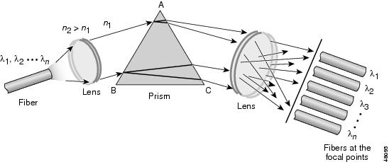
Prism diffraction
- based on dispersion
- different medium from fiber: encourages dispersion instead of dampening it ≡ power loss at the border
- lenses
- cannot be made compact
- focus length must be less than cm, such lenses cannot be made cheap
- Fresnels lenses require high index contrasts
- CWDM
Waveguide grating
- based on diffraction
- different λ are steered to different angles
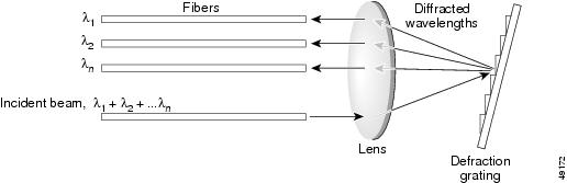
Arrayed waveguide grating
- based on interference
- incoming grey signal
- grey signal passes empty space
- grey signal is split over several paths of different length ≡ different phase shift, 2πn difference of wave front
- signals interfere with each other
- different wavelengths interfere in different locations
- 1 → 5 ≡ demultiplexer, 5 → 1 ≡ multiplexer
- uniform insertion loss: does not depend on channel count
- temperature sensitive
- depend on polarization
- scalable channel count and spectral shape
- cost effective mass productivity: semiconductor based
- DWDM

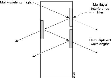
Thin film filters
- CWDM
- low channel count WDM: loss due to reflection
- TFF filters light serially: target λ is passed, the rest is reflected into next TFF